A Predictive Dead Time Generation Circuit

A technology of dead time and circuit generation, which is applied in the direction of electrical components, adjustment of electric variables, high-efficiency power electronic conversion, etc., can solve the problem that the dead time cannot reach the optimal value, and achieve the effect of reducing power consumption and optimizing length

Active Publication Date: 2020-09-15
UNIV OF ELECTRONICS SCI & TECH OF CHINA
View PDF5 Cites 0 Cited by
  • Summary
  • Abstract
  • Description
  • Claims
  • Application Information

AI Technical Summary

Problems solved by technology

[0007] Aiming at the problem of power consumption caused by the fact that the dead time in the traditional fixed dead time generation circuit cannot reach the optimal value, the present invention proposes a predictive dead time generation circuit, which optimizes the dead time margin while ensuring the dead time margin. length of dead time, thereby reducing power consumption

Method used


Image

  • A Predictive Dead Time Generation Circuit
  • A Predictive Dead Time Generation Circuit
  • A Predictive Dead Time Generation Circuit

Examples


Embodiment Construction

[0052] The present invention will be described in detail below in conjunction with the accompanying drawings and specific embodiments.
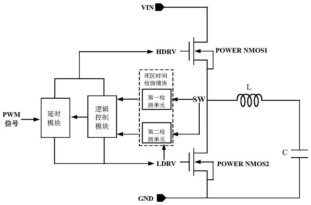
[0053] The idea of ​​the predictive dead-time generation circuit proposed by the present invention is to judge whether the dead-time reaches an optimal value through the working state of the current cycle, so as to determine whether the dead-time of the next cycle will increase or decrease. Such as figure 2 The schematic diagram of the dead time detection circuit is shown, and the predictive dead time generation circuit includes three parts: dead time detection module, logic control module and delay module. The pulse width modulation signal PWM of the DC-DC converter is delayed by the delay module and combined with the signal generated by the logic control module to generate the upper power tube drive signal HDRV and the lower power tube drive signal LDRV. The dead time detection module is used to detect the dead time between the upper powe...


PUM


Abstract

A predictive dead zone time generating circuit belongs to the technical field of electronic circuits. The dead time detection module is used to detect the dead time when the upper power tube is turned off and the lower power tube is turned on, and the dead time when the lower power tube is turned off and the upper power tube is turned on, and generates the first The detection signal and the second detection signal, the logic control module changes the output of the delay module according to the judgment result of the dead time detection module, thereby changing the dead time between the upper power tube driving signal and the lower power tube driving signal. The predictive dead time generation circuit proposed by the present invention can optimize the length of the dead time while ensuring the dead time margin by adjusting the dead time, thereby reducing power consumption.

Description

technical field [0001] The invention belongs to the technical field of electronic circuits, and in particular relates to a predictive dead zone time generating circuit, which can be used for a DC-DC control converter. Background technique [0002] As the battery volume of electronic devices becomes smaller and the voltage becomes lower and lower, the requirements for the working efficiency of switching power supplies are getting higher and higher. Various techniques are used in switching power supply technology to improve efficiency. Among them, the synchronous rectification technology does not use the traditional diode rectification, but the MOSFET tube with low conduction voltage drop for rectification, thereby reducing the conduction loss of the switching power supply system and improving the conversion efficiency of the switching power supply system. Since the MOSFET tube does not have the unidirectional conduction characteristics of the diode, it is necessary to add a ...

Claims


Application Information

Patent Timeline
Patent Type & Authority Patents(China)
IPC IPC(8): H02M1/38H02M3/158
CPCH02M1/08H02M1/38H02M3/158Y02B70/10H02M3/156H02M3/1588H02M1/0032
Inventor 周泽坤王韵坤袁东李世磊王卓张波
Owner UNIV OF ELECTRONICS SCI & TECH OF CHINA
Why Eureka
Try Eureka