Hybrid power system and vehicle

A hybrid power system, No. 1 technology, which is applied in power units, vehicle components, pneumatic power units, etc., can solve problems such as power loss and other functional drive modes that are single, and the pure electric mode No. 2 motor cannot be adjusted in speed, so as to avoid The effect of No. 2 motor follow-up, improving power and economy, and improving efficiency

Inactive Publication Date: 2019-05-24
ZHENGZHOU YUTONG BUS CO LTD
View PDF11 Cites 0 Cited by
  • Summary
  • Abstract
  • Description
  • Claims
  • Application Information

AI Technical Summary

Problems solved by technology

[0007] The purpose of the present invention is to provide a hybrid power system to solve the technical problems in the prior art that the No. 2 motor in the pure electric mode cannot be adjusted by variable speed, and the No. 2 motor in the high-speed driving mode will cause power loss due to rotation. ; The object of the present invention is also to provide a vehicle using the above-mentioned hybrid system

Method used


Image

  • Hybrid power system and vehicle
  • Hybrid power system and vehicle
  • Hybrid power system and vehicle

Examples


Embodiment 1

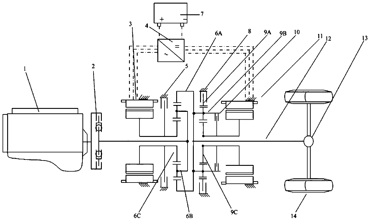
[0027] Embodiment 1 of the vehicle of the present invention: the vehicle includes a vehicle body and a hybrid system, such as figure 1 As shown, the hybrid system includes an engine 1, a torsional shock absorber 2, a No. 1 motor 3, a motor controller 4, a first brake (or clutch) 5, a first planetary ring gear 6A, and a first planetary planet carrier 6B. , the first planetary row sun gear 6C, the power supply 7, the second brake (or clutch) 8, the second planetary row ring gear 9A, the second planetary row carrier 9B, the second planetary row sun gear 9C, the first clutch 10 , No. two motor 11, output shaft 12, rear axle 13, tire 14. The output shaft of the engine 1 is connected with the first planetary planet carrier 6B through the torsional shock absorber 2; the rotor of the No. 1 motor 3 is connected with the first brake (or clutch) 5 and the first planetary sun gear 6C; the first The planetary gear ring gear 6A is connected with the second planetary planetary carrier 9B an...

Embodiment 2

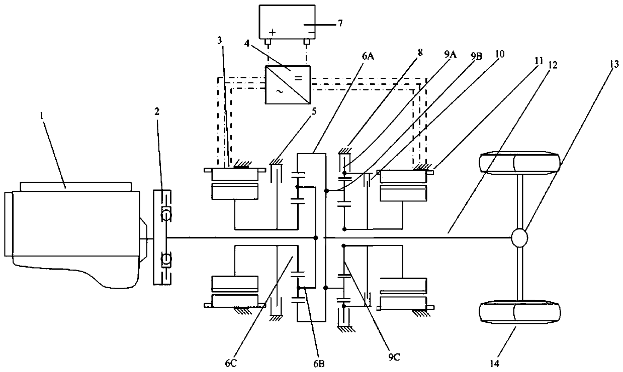
[0044] Embodiment 2: The difference with Embodiment 1 is that, as figure 2 As shown, one end of the first clutch 10 is connected to the second planetary gear ring gear 9A, and the other end is connected to the rotor of the second motor 11. Its working process is similar to that of Embodiment 1 and will not be repeated here.

Embodiment 3

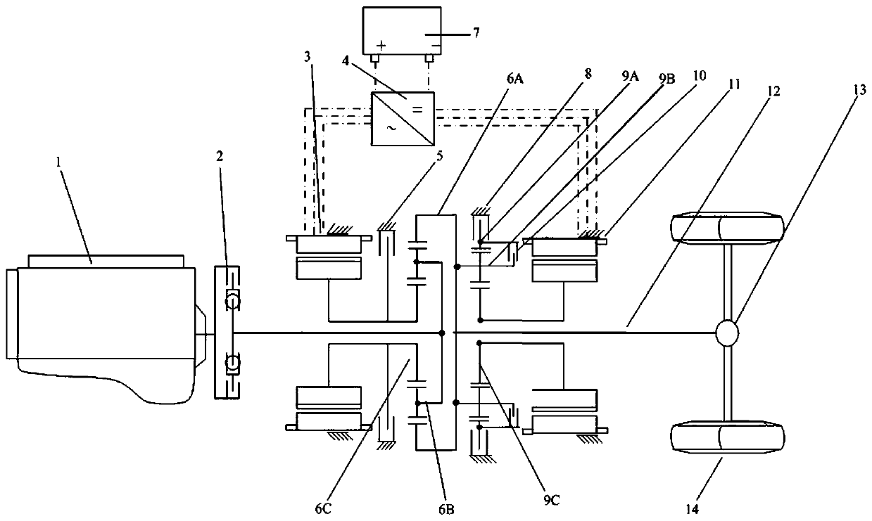
[0045] Embodiment 3: The difference with Embodiment 1 is that, as image 3 As shown, one end of the first clutch 10 is connected to the second planetary ring gear 9A, and the other end is connected to the second planetary carrier 9B. The working process of the first clutch 10 is similar to that of Embodiment 1, and will not be repeated here.

[0046] In other embodiments: the first and second brakes (or clutches) can also be replaced by other types of braking devices; the input and output components of the front planetary row can also be changed, for example, can be changed to utilize the planetary carrier for output.

[0047] The embodiments of the hybrid power system of the present invention are the same as the embodiments of the hybrid power system in the embodiments of the vehicle of the present invention, and will not be repeated here.


PUM


Abstract

The invention relates to a hybrid power system and a vehicle. The hybrid power system is characterized in that a braking device is connected on a rear gear ring to control the rotation and stop of therear gear ring; separation and connection of two parts among a rear sun wheel, a gear ring and a planet carrier are realized by a clutch; speed control of a No.2 motor is realized through the cooperation of the two braking devices to meet the needs of high-speed driving and heavy-duty climbing; through the synergy of two control devices and one clutch, free switching of multiple drive modes suchas pure electric, multiple hybrid, engine direct drive and multiple energy recovery modes can be realized, and thus power system efficiency is increased; that the No. 2 motor follows in high speed operation can be avoided, and consequently, energy waste is avoided, and power performance and economy of hybrid vehicles are significantly improved.

Description

technical field [0001] The invention relates to a hybrid power system and a vehicle. Background technique [0002] At present, the rapid development of new energy vehicles has become a research hotspot in the current automotive industry. According to the different structural arrangements of the transmission system, the existing hybrid power systems are divided into three types: series, parallel, and hybrid. The hybrid hybrid system can take into account the advantages of series and parallel systems, and is favored. The most successful hybrid hybrid system is undoubtedly Toyota's THS system, but THS uses a single-mode power split with a single planetary row structure. Mode leads to low transmission efficiency at high speeds. GM has developed a double-row or multi-row planetary power system. Although the transmission efficiency at low and high speeds has been improved, the system structure is complex and difficult to control. [0003] The Chinese patent with application publi...

Claims


Application Information

Patent Timeline
Patent Type & Authority Applications(China)
IPC IPC(8): B60K6/365B60K6/38
Inventor 王印束刘小伟王富生吴胜涛王兴
Owner ZHENGZHOU YUTONG BUS CO LTD
Why Eureka
Try Eureka