
Geological survey construction method and structure

A technology of geological survey and construction method, applied in the field of geological survey, can solve problems such as soil is easily washed away by rain, road traffic is greatly affected, iron plate displacement and deformation, etc., to ensure normal traffic, convenient excavation operation, reduce effect of influence

Active Publication Date: 2020-12-22
广东有色工程勘察设计院
View PDF0 Cites 0 Cited by
  • Summary
  • Abstract
  • Description
  • Claims
  • Application Information

AI Technical Summary

Problems solved by technology

[0005] A drilling operation generally takes a few days to complete. In order not to affect the normal traffic on the road during the day, iron plates are generally laid or covered with soil at the survey location. However, iron plates are prone to displacement and deformation after vehicles run over them, which is harmful to safety. Cause hidden dangers; in heavy rain weather, the soil used to cover the pit is easily washed away by rainwater, which has a great impact on road traffic

Method used


Image

  • Geological survey construction method and structure
  • Geological survey construction method and structure

Examples


Embodiment 1

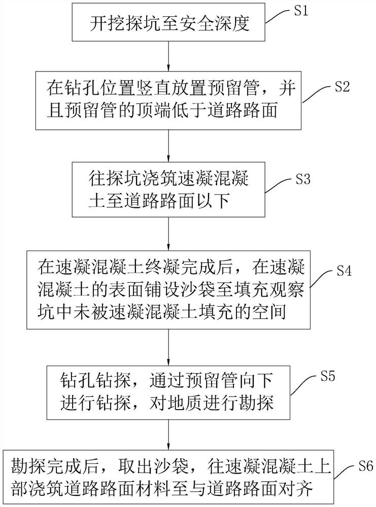
[0043] Embodiment 1: geological survey construction method, such as figure 1 shown, including the following steps:

[0044] S1: Excavate the exploration pit 1 to a safe depth, that is, delineate the excavation range with an area of ​​80cm*120cm at the position where drilling survey is required, and manually excavate the exploration pit 1 to 2.8m-3.2m within the excavation range ( Such as a safe depth of 3m), the buried depth of general urban pipelines is within this range. Excavation pit 1 can be excavated to this depth to ensure that the impact of drilling operations on urban pipelines can be avoided. Whether the position of the hole work will conflict with the original urban pipeline, if so, re-determine the drilling position and re-excavate the exploration pit 1, and the top of the exploration pit 1 will increase from the area of ​​80cm*120cm with the excavation depth Gradually decrease, the side length of the area covered by the bottom of the pit 1 must not be less than t...

Embodiment 2

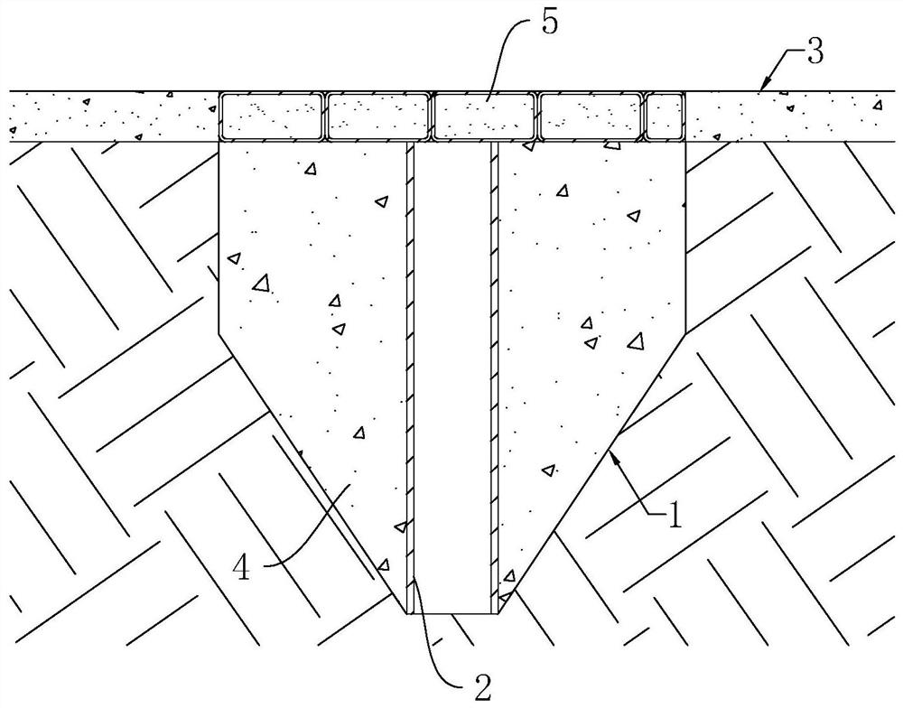
[0054] Embodiment 2: geological survey construction structure, such as figure 2 As shown, including the exploration pit 1 excavated on the road surface 3, the depth of the exploration pit 1 is 2.8m-3.2m (such as 3m), and the area of ​​its top from 80cm*120cm gradually decreases with the increase of the excavation depth. The side length of the area covered by the bottom of the pit 1 is larger than the diameter of the reserved pipe 2 placed in the pit 1 subsequently, so that the reserved pipe 2 can smoothly touch the bottom of the pit 1 .

[0055] A reserved pipe 2 is vertically arranged in the exploration pit 1, the top of the reserved pipe 2 is lower than the road surface 3, and the distance between the top of the reserved pipe 2 and the road surface 3 is 28cm-32cm (such as 30cm). Stay pipe 2 selects PVC pipe or steel pipe for use, and its diameter is greater than the drilling tool diameter that carries out drilling operation.

[0056] Quick-setting concrete 4 is poured betw...


PUM

PropertyMeasurementUnit
depthaaaaaaaaaa
thicknessaaaaaaaaaa

Abstract

The invention relates to the field of geological survey, in particular to a geological survey construction method and structure. During night survey operations, manual excavation to safe depth ensuresthat subsequent drilling cannot damage existing underground pipelines and the site can resume the use function if the construction work is not completed within the valid time, and reserved pipes reserve the operation position for subsequent drilling operations; quick-setting concrete is first poured 30cm below the road surface in the absence of drilling, sandbags with good gradation are used to fill the pit after the concrete is finally set, vehicles and pedestrians can pass through normally during the day, the sandbags are less prone to shift when run over by the vehicle, the flatness of thesandbags is adjusted automatically under pressure, and alignment with the road surface is improved; during heavy rain, filling material in the sandbags is not easy to be lost in the rain, and normalpassage of the road surface is ensured.

Description

technical field [0001] The invention relates to the field of geological survey, in particular to a geological survey construction method and structure. Background technique [0002] The subway refers to the urban rail transit system that mainly runs underground, and is an important part of the urban transportation network. [0003] Before the construction of the subway, the geology of the rock and soil along the construction of the subway must be surveyed. The existing construction method is generally to drill a certain depth (according to the design requirements) in the ground for geological survey. Since most subway lines need to pass through densely populated residential areas, there are generally complex pipelines in the survey location, and direct geological drilling will cause damage to the original pipeline system. Generally, a test pit will be excavated at the preset drilling position, and the drilling operation will be carried out after ensuring that no damage will...

Claims


Application Information

Patent Timeline
Patent Type & Authority Patents(China)
IPC IPC(8): E01C23/09G01N1/08
Inventor 乔高乾沈秋华曾令浓徐力峰魏欣欣
Owner 广东有色工程勘察设计院
Learn More