Al technical title is built by PatSnap Al team. It summarizes the technical point description of the patent document.
A crucible furnace and spiral technology, which is applied in the field of spiral inner wall crucible furnaces, can solve the problems of increased use cost, influence on the service life of the crucible, damage to the crucible furnace, etc. The effect of improving the efficiency of the energy cycle
Pending Publication Date: 2019-05-24
昆山北陆技研工业设备有限公司
View PDF5 Cites 1 Cited by
Summary
Abstract
Description
Claims
Application Information
AI Technical Summary
This helps you quickly interpret patents by identifying the three key elements:
Problems solved by technology
Method used
Benefits of technology
Problems solved by technology
Since the flame of the burner rises directly along the inner wall to heat the crucible, the part of the crucible close to the lower part of the burner will be heated quickly, while the upper part farther away from the burner will be heated relatively slowly, which will affect the melting and temperature of the material in the crucible ;The phenomenon of hot bottom and cold top is particularly prominent in this type of crucible furnace, and if things go on like this, the crucible in the furnace has different surface loads, so it has a great impact on the service life of the crucible, resulting in increased use costs
[0004] In addition, during the use of the existing crucible furnace, hot melt liquid will inevitably leak into the furnace. If the crucible furnace is not found and shut down in time, it will easily cause damage to the crucible furnace and threaten the safety of the staff.
Method used
Image
Click on the blue label to locate the original text in one second.
Reading with bidirectional positioning of images and text.
Examples
Embodiment Construction
[0021] The present invention is described in detail below in conjunction with accompanying drawing and specific embodiment:
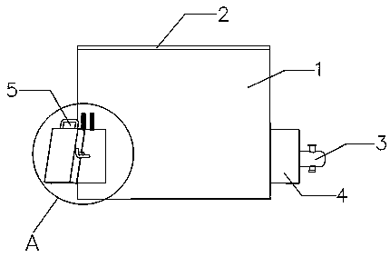
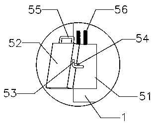
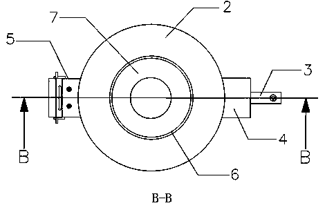
[0022] figure 1 with image 3 A spiral inner wall crucible furnace is shown, comprising a furnace body 1, the furnace body 1 is made of a refractory material into a column, and its exterior is wrapped by an iron sheet; A crucible 6 is placed, the bottom of the crucible 6 is supported by a crucible seat 11 arranged at the center of the bottom of the furnace 9, and the top of the crucible 6 is pressed and fixed by a gland 2 arranged on the top of the furnace body 1. The hearth 9 is sealed, the center of the gland 2 is provided with a soup intake 7 communicating with the inside of the crucible 6, the outer side of the furnace body 1 near the bottom is provided with a flame port 4, and the end surface of the flame port 4 is provided with A connecting hole 10 communicating with the furnace 9, a burner 3 is installed in the connecting hole 10, and the burne...
PUM
Abstract
The invention discloses a spiral inner wall crucible furnace. The spiral inner wall crucible furnace comprises a furnace body, a hearth is arranged in the furnace body, a crucible is placed in the hearth, the top of the crucible is compressed and fixed through a gland, a flame opening is formed in the position, close to the bottom, of the outer side of the furnace body, a burner is mounted on theflame opening, a spiral guide groove from bottom to top is formed in the hearth along the wall surface of the hearth, a vertical exhaust channel is formed in the position, above the spiral guide groove, of the wall surface of the hearth, the top end of the exhaust channel communicates with the hearth, and the tail end of the exhaust channel communicates with a connecting hole; and a leakage detection alarming opening communicating with the hearth is formed in the outer side of the furnace body. According to the spiral inner wall crucible furnace, the crucible heating efficiency is improved, the dissolving speed is increased, the service life of a crucible is longer, the up-down temperature in the crucible is uniform, the defective rate of a product is increased, waste heat can be recycledfor exhausting, the energy circulating efficiency is improved, the energy-saving effect is achieved, meanwhile, through design of the leakage detection alarming opening, the safety coefficient of thecrucible furnace is increased, and the service life of the crucible furnace is prolonged.
Description
technical field [0001] The invention relates to the field of crucible furnaces, in particular to a crucible furnace with a spiral inner wall. Background technique [0002] The crucible furnace is a furnace with a crucible in the hearth and a fixed or tiltable furnace body. It is mainly used for sintering, melting and analysis of metal, non-metal and compound materials. [0003] At present, the inner wall of the crucible furnace on the market is vertical to the hearth. Its working principle is that the burner located under the side of the furnace emits flames to heat the crucible in the furnace from below, and the exhaust gas generated after the fuel burns It is discharged from the chimney installed on the furnace body. Since the flame of the burner rises directly along the inner wall to heat the crucible, the part of the crucible close to the lower part of the burner will be heated quickly, while the upper part farther away from the burner will be heated relatively slowly, ...
Claims
Application Information
Patent Timeline
Application Date:The date an application was filed.
Publication Date:The date a patent or application was officially published.
First Publication Date:The earliest publication date of a patent with the same application number.
Issue Date:Publication date of the patent grant document.
PCT Entry Date:The Entry date of PCT National Phase.
Estimated Expiry Date:The statutory expiry date of a patent right according to the Patent Law, and it is the longest term of protection that the patent right can achieve without the termination of the patent right due to other reasons(Term extension factor has been taken into account ).
Invalid Date:Actual expiry date is based on effective date or publication date of legal transaction data of invalid patent.