Method and device for detecting line optical difference protection ratio brake curve

A protection device, ratio braking technology, applied in the direction of measuring device, measuring electricity, measuring electrical variables, etc., can solve the problems of inconsistency of output current phase, difficult operation, different current phase, etc., to ensure safe and stable operation, detection Precise results and avoid misoperation

Pending Publication Date: 2019-05-24
JINCHENG POWER SUPPLY COMPANY OF STATE GRID SHANXI ELECTRIC POWER
View PDF0 Cites 3 Cited by
  • Summary
  • Abstract
  • Description
  • Claims
  • Application Information

AI Technical Summary

Problems solved by technology

Although the "off-site joint debugging method" can detect channel performance, simulate line faults during empty charging or no-load, simulate weak feed function and remote tripping function, it has major defects: it cannot detect the most basic ratio braking characteristic of differential protection, The reasons are as follows:
[0004] 2. The output current phase of the two places is difficult to be consistent
Even if two relay protection testers of the same model are used, due to the different initial phase angles, the output current phases will be different, resulting in the inability to match the currents on both sides.
[0005] 3. The cooperation

Method used


Image

  • Method and device for detecting line optical difference protection ratio brake curve
  • Method and device for detecting line optical difference protection ratio brake curve
  • Method and device for detecting line optical difference protection ratio brake curve

Examples


Embodiment Construction

[0032] In order to make the technical problems, technical solutions and beneficial effects to be solved by the present invention clearer, the present invention will be further described in detail in combination with the embodiments and accompanying drawings. It should be understood that the specific embodiments described here are only used to explain the present invention, not to limit the present invention. The technical solutions of the present invention will be described in detail below in conjunction with the embodiments and accompanying drawings, but the scope of protection is not limited thereto.

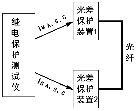
[0033] like Figure 3-Figure 6 As shown, a device for detecting the braking curve of the light difference protection ratio of a line includes a relay protection tester 1, a first light difference protection device 2, a second light difference protection device 3 and an optical fiber 4, and the first light difference protection device 2 is connected to the second optical diffe...


PUM


Abstract

The invention relates to the field of power system relay protection and discloses a method and a device for detecting a line optical difference protection ratio brake curve. The method specifically includes: putting two optical difference protection devices at a same place, connecting the same through optical fiber, setting starting current, knee point current and slope of the optical difference protection devices, starting a six-phase differential function of a relay protection tester to output three-phase current to the optical difference protection devices respectively, and using a ratio brake curve automatic drawing function of the relay protection tester for detection. The device overcomes distance and instrument limitation, does not need multiple-person cooperation and is simple andconvenient to operate, accurate in detection result and free of optical fiber channel and outside interference. The method and the device realize ratio brake characteristic detection to enable opticaldifference protection experiments to be more complete, avoid optical difference protection maloperation and ensure safe and stable running of a power grid.

Description

technical field [0001] The invention relates to the field of relay protection of electric power systems, in particular to a method for detecting the ratio braking curve of a line light difference protection device, and a device for detecting the ratio braking curve of a line light difference protection device. Background technique [0002] Due to the collection of electrical quantities on both sides of the line, the optical fiber differential protection has a fast action speed, high sensitivity, and is not affected by changes in the operating mode. As the main protection of the line, it is more and more widely used in the power grid. like figure 1 It is the schematic diagram of light difference protection. In order to improve the selectivity and sensitivity of protection, the line light difference protection device adopts ratio braking differential protection. It is of great significance to test its ratio braking characteristics. However, since the two optical difference pr...

Claims


Application Information

Patent Timeline
IPC IPC(8): G01R31/00
Inventor 张锴郝骏春杨晋彪姚辉罗长明吴谢东郭志锐郑江卫学峰张丽丽李学军柴云峰陈大欢贺敏原康赵梓帆张昕蕾
Owner JINCHENG POWER SUPPLY COMPANY OF STATE GRID SHANXI ELECTRIC POWER
Why Eureka
Try Eureka