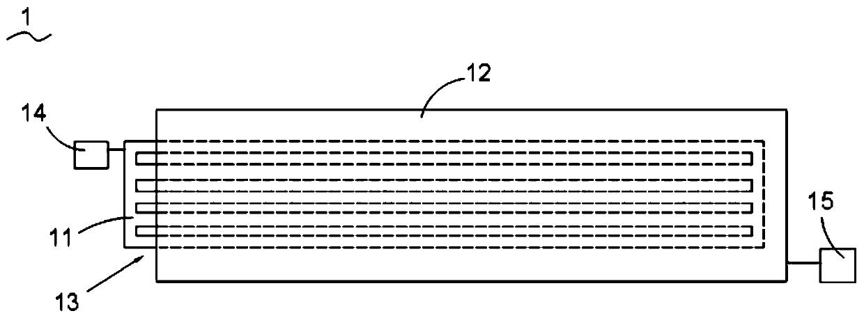
WAT test device for detecting metal connecting line hillocks, preparation method and test method
A metal connection and test device technology, which is applied in the field of WAT test devices for detecting metal connection uplifts, and can solve problems such as process problems
- Summary
- Abstract
- Description
- Claims
- Application Information
AI Technical Summary
Problems solved by technology
Method used
Image
Examples
preparation example Construction
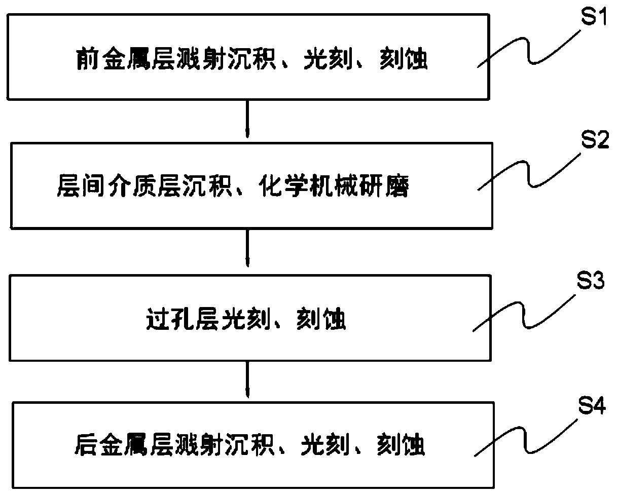
[0034] see figure 2 , figure 2 Shown is the flow chart of the preparation method of the WAT test device for detecting metal wire bumps according to the present invention. The preparation method of the WAT testing device 1 for detecting metal connection bulging includes:
[0035] Executing step S1: sputtering deposition of the front metal layer 11, photolithography, etching;
[0036] Executing step S2: deposition of interlayer dielectric layer 13, chemical mechanical polishing;
[0037]Executing step S3: photolithography and etching of the via layer;
[0038] Step S4 is performed: sputtering deposition, photolithography, and etching of the back metal layer 12 .
[0039] In order to reveal the technical solution of the present invention more intuitively and highlight the beneficial effects of the present invention, the structure and working principle of the WAT test device 1 for detecting metal connection bulge described in the present invention are described in conjunctio...
no. 1 approach
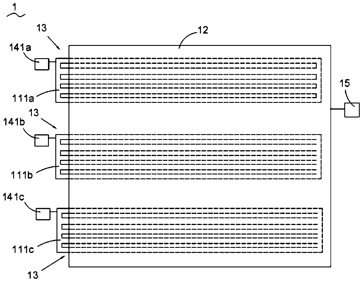
[0041] As a first embodiment of the present invention, non-limiting enumeration, for example, the WAT test device 1 for detecting metal wiring bumps includes a front metal layer 11, and the front metal layer 11 has a first preset line width The metal line 111a of the second preset line width, the metal line 111b of the second preset line width, and the metal line 111c of the third preset line width.
[0042] see image 3 , image 3 Shown is a schematic structural view of a WAT testing device for detecting metal wire bumps according to the first embodiment of the present invention. The WAT test device 1 for detecting metal wiring bumps includes a front metal layer 11 and a back metal layer 12, the front metal layer 11 has a metal line 111a with a first preset line width, a second preset line width The metal line 111b of the metal line 111b of the third preset line width, and the interlayer dielectric layer 13 is set between the front metal layer 11 and the back metal layer ...
no. 2 approach
[0048] As a second embodiment of the present invention, non-limiting enumeration, for example, the WAT test device 1 for detecting metal wiring bumps includes a front metal layer 11, and the front metal layer 11 has a fourth preset line width The metal line 112a of the fifth predetermined line width and the metal line 112b of the fifth preset line width. Wherein, the fourth predetermined line width of the metal line 112a of the front metal layer 11 and the fifth predetermined line width of the metal line 112b of the front metal layer 11 are the most concerned metal line widths in the semiconductor device manufacturing process.
[0049] see Figure 4 , Figure 4 Shown is a schematic structural diagram of a WAT testing device for detecting metal wire bumps according to the second embodiment of the present invention. The WAT test device 1 for detecting metal wiring bumps includes a front metal layer 11 and a back metal layer 12, the front metal layer 11 has a metal line 112a ...
PUM
| Property | Measurement | Unit |
|---|---|---|
| Line width | aaaaa | aaaaa |
| Spacing | aaaaa | aaaaa |
Abstract
Description
Claims
Application Information
 - R&D
- Intellectual Property
- Life Sciences
- Materials
- Tech Scout
- Unparalleled Data Quality
- Higher Quality Content
- 60% Fewer Hallucinations
Browse by: Latest US Patents, China's latest patents, Technical Efficacy Thesaurus, Application Domain, Technology Topic, Popular Technical Reports.
© 2025 PatSnap. All rights reserved.Legal|Privacy policy|Modern Slavery Act Transparency Statement|Sitemap|About US| Contact US: help@patsnap.com


