Eureka AIR delivers breakthrough ideas for toughest innovation challenges, trusted by R&D personnel around the world.

Novel ultra-wideband power divider based on LTCC

A technology of ultra-wideband and power divider, applied in the microwave field, can solve the problems of inability to realize wideband and ultra-wideband applications, poor balance of ring bridges, narrow operating frequency range, etc., to achieve mass production, small return loss, The effect of output signal power and phase consistency

Inactive Publication Date: 2019-05-24
NANJING UNIV OF SCI & TECH
View PDF6 Cites 3 Cited by
  • Summary
  • Abstract
  • Description
  • Claims
  • Application Information

AI Technical Summary

Problems solved by technology

[0003] As an important role in the radio frequency communication system, the power splitter has higher and higher requirements for its miniaturization, broadband, and low loss. As early as 1974, the structure of the ring bridge was first proposed by scholars, and more and more scholars studied it. More and more, until now, the ring bridge has also been used in various radio frequency integrated circuits, but the balance of the ring bridge is poor, so its application frequency range is narrow, and the bandwidth is generally only between 10% and 20%. space, and relatively large
In order to make the power divider have better performance, some scholars proposed a new type of Wilkinson power divider in 1960. This power divider improves the isolation of each port, and can achieve matching, and the structure is relatively simple. It is a kind of power splitter that is commonly used in the field of microwave technology at present, but its disadvantage is that the working frequency band is narrow, and it cannot realize the application of broadband or even ultra-wideband. Therefore, it is of great research significance to study ultra-wideband power splitters.

Method used


Image

  • Novel ultra-wideband power divider based on LTCC
  • Novel ultra-wideband power divider based on LTCC
  • Novel ultra-wideband power divider based on LTCC

Examples


Embodiment

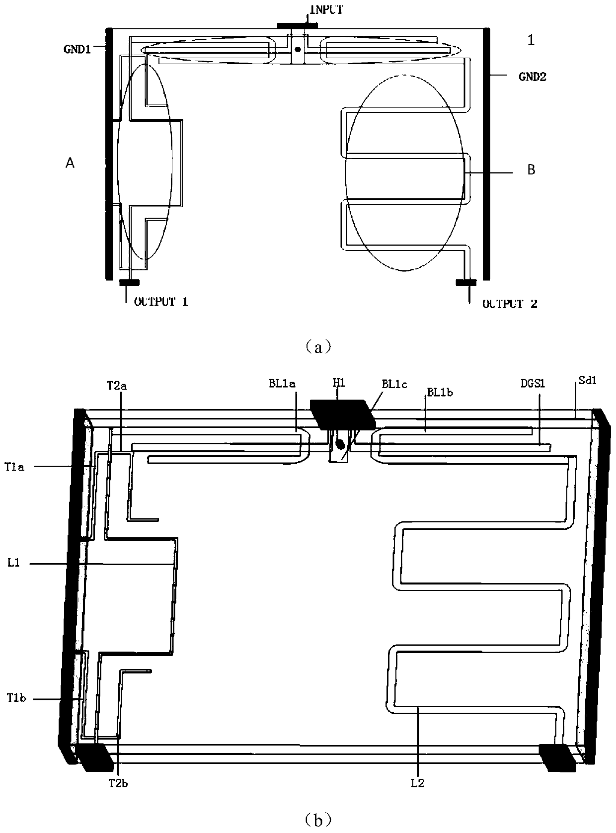
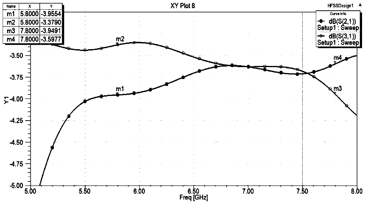
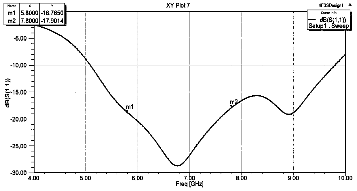
[0033] In the embodiment of the present invention, a novel ultra-wideband power divider based on LTCC has a size of 8.6mm×11.8mm×1.5mm and an operating frequency of 5.8GHz˜7.8GHz. Obtain the amplitude-frequency characteristic curve, standing wave curve, and output phase curve of each output port of the ultra-wideband power divider as follows: figure 2 , 3 , 4 shown.

[0034] Depend on figure 2 , image 3 , Figure 4 It can be seen that the amplitude-frequency characteristics of the output waveforms of the first output port OUTPUT 1 and the second output port OUTPUT2 are basically the same, the passband is relatively flat, the port insertion loss is less than 1dB, and the return loss of the first input port INPUT is better than 17dB. The signal output phase difference of the first output port OUTPUT 1 and the second output port OUTPUT 2 is +7°.

[0035] In summary, the present invention adopts low-temperature co-fired ceramic (LTCC) process technology to realize three-di...


PUM


Abstract

The invention discloses a novel ultra-wideband power divider based on LTCC. The power divider comprises an ultra-wideband balun and a 180-degree ultra-wideband phase shifter, wherein the ultra-wideband balun part is formed by three ports of a strip line-defected ground structure, the phase shifter part is formed by a folded transmission line and a reference straight wire, an unbalanced output portof the ultra-wideband balun is connected with an input end of a phase shifting channel of the wideband 180-degree phase shifter, and another unbalanced output port of the balun is connected with an input end of the reference straight wire of the phase shifter, so that the power divider with ultra-wideband performance is formed. The ultra-wideband power divider has the advantages of small volume,simple circuit structure, ability of realizing large-scale production, wide bandwidth, flat passband, low echo loss and consistent power and phase of output signals of the output port. In addition, the ultra-wideband power divider is convenient to install in the using process, capable of independently serving as a component and applicable to a feed network of a power amplifier and an array antenna.

Description

technical field [0001] The invention belongs to the field of microwave technology, in particular to a novel ultra-wideband power splitter based on LTCC. Background technique [0002] The introduction of ultra-wideband technology can be traced back to the late 1950s. With the accuracy requirements of positioning systems in the military field, ultra-wideband began to attract people's attention. With the development of modern communication technology, the application range of wireless communication is becoming wider and wider. The bandwidth range of electronic components in the past can no longer be widely used in modern communication systems. Therefore, ultra-wideband technology has gradually attracted the attention of domestic and foreign scholars. What follows is the generation of various ultra-wideband electronic devices in wireless communication systems. [0003] As an important role in the radio frequency communication system, the power splitter has higher and higher req...

Claims


Application Information

Patent Timeline
IPC IPC(8): H01P5/16
Inventor 方洁常钰敏赵子豪杨冕曹小芝戴永胜
Owner NANJING UNIV OF SCI & TECH
Why Eureka
Eureka Blog
Learn More