Synchronous rectifier circuit of wireless charging receiving terminal

A synchronous rectification and wireless charging technology, applied in the direction of high-efficiency power electronic conversion, electrical components, output power conversion devices, etc., can solve the problems of loss, loss growth, heat generation, etc., to achieve high rectification efficiency and improve the effect of heating problems

Active Publication Date: 2019-05-24
CRM ICBG (WUXI) CO LTD
View PDF5 Cites 6 Cited by
  • Summary
  • Abstract
  • Description
  • Claims
  • Application Information

AI Technical Summary

Problems solved by technology

[0003] The conduction voltage drop of the rectifier diode is 0.7V, so the loss of the rectifier module with the full-bridge diode structure will multiply due to the incre

Method used


Image

  • Synchronous rectifier circuit of wireless charging receiving terminal
  • Synchronous rectifier circuit of wireless charging receiving terminal
  • Synchronous rectifier circuit of wireless charging receiving terminal

Examples


Embodiment Construction

[0038] In order to understand the technical content of the present invention more clearly, the following examples are given in detail.

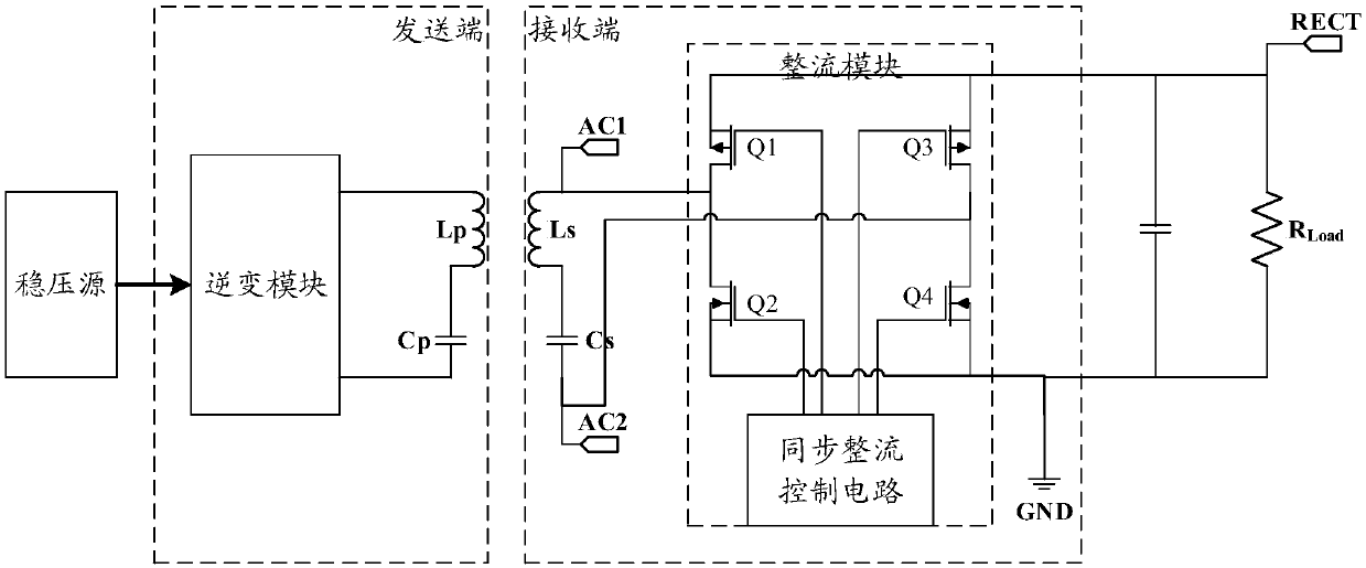
[0039] The synchronous rectification circuit of the wireless charging receiver is used to realize the rectification function of the wireless charging receiver, and the synchronous rectification circuit is connected between the resonant circuit and the load of the wireless charging receiver, including a MOS transistor rectification circuit and a synchronous rectification The control circuit is connected to each other, and the synchronous rectification control circuit realizes the control of the working sequence of each MOS transistor in the MOS transistor rectification circuit by controlling the driving voltage input to each MOS transistor in the MOS transistor rectification circuit.

[0040] In a preferred embodiment, the MOS transistor rectifier circuit is a full-bridge MOS transistor rectifier circuit, and the full-bridge MOS transistor rect...


PUM


Abstract

The invention relates to a synchronous rectifier circuit of a wireless charging receiving terminal, which is used to realize the rectification function of a wireless charging receiver. The synchronousrectifier circuit is connected between a resonant circuit of the wireless charging receiver and a load, and includes an MOS transistor rectifier circuit and a synchronous rectifier control circuit. The synchronous rectifier control circuit controls the working sequence of the MOS transistors in the MOS transistor rectifier circuit by controlling the driving voltages input to the MOS transistors in the MOS transistor rectifier circuit, so that the synchronous rectifier circuit has a rectification effect consistent with a preset effect. By adopting the synchronous rectifier circuit of the wireless charging receiving terminal of the invention, the rectification efficiency is higher than that of the diode rectifier circuit in the prior art, and the heating problem caused by diode rectification loss can be significantly improved. The synchronous rectifier circuit is simple and convenient, needs no additional software control, and can be used as an independent module to replace the diode rectifier module.

Description

technical field [0001] The present invention relates to the field of wireless charging, in particular to the field of rectification control of a wireless charging receiver, and specifically refers to a synchronous rectification circuit of a wireless charging receiving end. Background technique [0002] Wireless charging is a technology that uses electromagnetic induction between planar coils to transmit energy between chargers and devices. In a common wireless charging system based on full-bridge diode rectification, the charger is called the sending end, the voltage regulator provides DC power for the sending end, and the inverter module converts the DC power into AC power. The oscillating electrical signal is generated on the series loop, and the alternating magnetic field is sent through the sending coil; the receiving coil Ls at the receiving end absorbs the energy of the alternating magnetic field, and an oscillating electrical signal is generated on the series loop wit...

Claims


Application Information

Patent Timeline
IPC IPC(8): H02M7/219H02M1/088
CPCY02B70/10
Inventor 王曌
Owner CRM ICBG (WUXI) CO LTD
Why Eureka
Try Eureka