Soiling solution recycling component and surface cleaning equipment

A technology of sewage and components, applied in cleaning equipment, suction nozzles, vacuum cleaners, etc., can solve the problems of flow to and affect the use, and achieve the effect of improving the comfort of use and increasing the safety of use.

Pending Publication Date: 2019-05-28
SUZHOU EUP ELECTRIC CO LTD
View PDF3 Cites 17 Cited by
  • Summary
  • Abstract
  • Description
  • Claims
  • Application Information

AI Technical Summary

Problems solved by technology

The accessories in the above two documents both realize the expansion of the scope of use of the vacuum cleaner using the ordinary dry vacuum motor, bu

Method used


Image

  • Soiling solution recycling component and surface cleaning equipment
  • Soiling solution recycling component and surface cleaning equipment
  • Soiling solution recycling component and surface cleaning equipment

Examples


Embodiment Construction

[0035] In order to describe the technical content, structural features, achieved goals and effects of the invention in detail, the following will be described in detail in conjunction with the embodiments shown in the accompanying drawings.

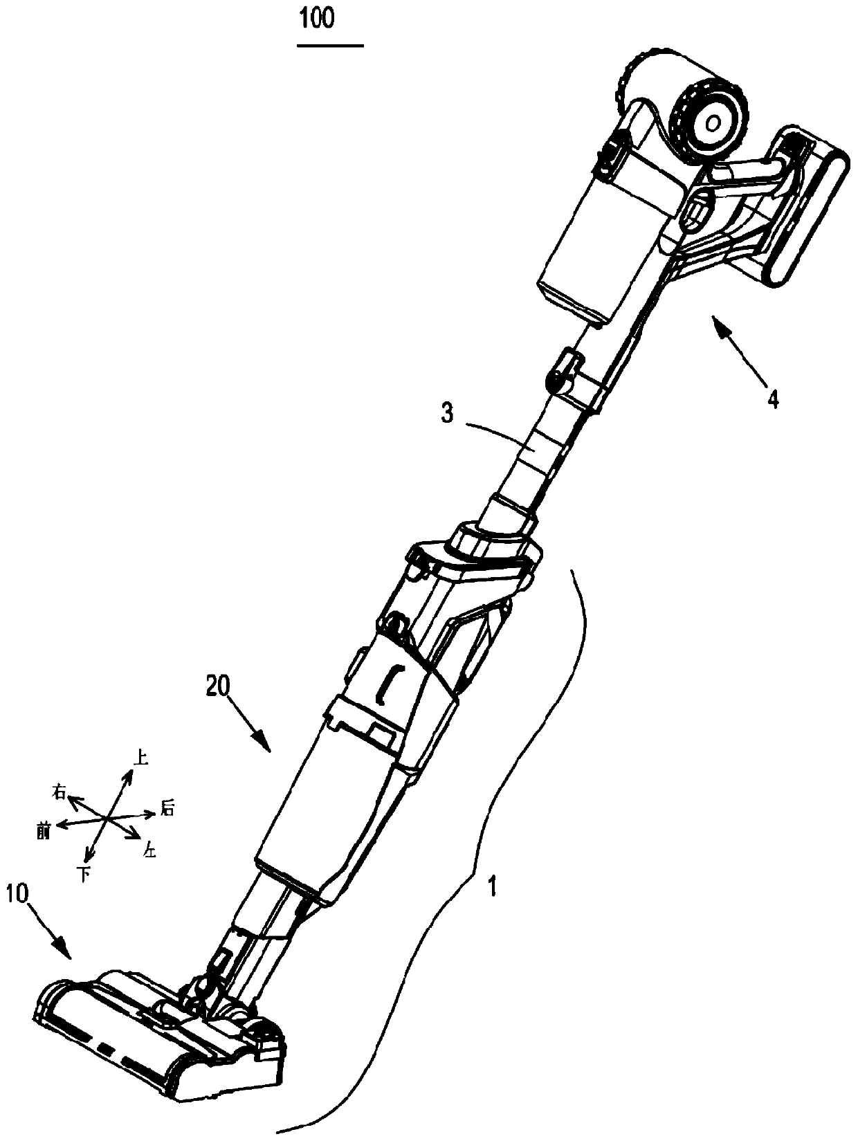
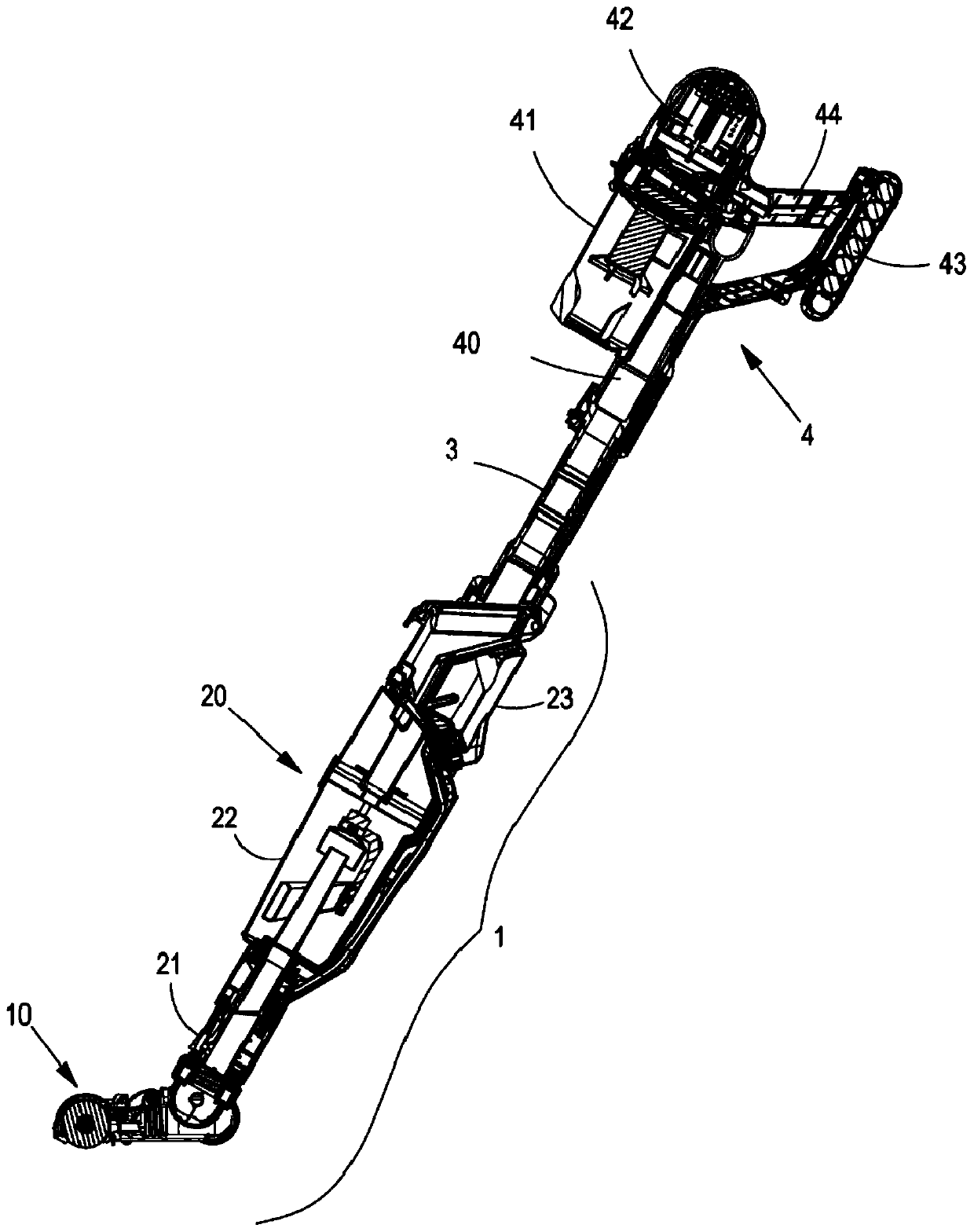
[0036] figure 1It is a three-dimensional schematic view showing a surface cleaning device 100 according to an embodiment of the present invention. The surface cleaning device 100 can realize spraying cleaning liquid on the surface to be cleaned while sucking the dirty liquid and air on the surface to be cleaned into the The processing is carried out inside the machine, that is, it has the functions of a vacuum cleaner and a scrubber. The surface cleaning device 100 includes three parts: a cleaning head device 1 , a hollow hard tube 3 and a hand-held vacuum cleaner 4 . The three parts are detachable, and the three parts are fluidly connected and electrically connected after assembly. For purposes of description relative to the figures, th...


PUM


Abstract

The invention discloses a soiling solution recycling component and surface cleaning equipment. The component comprises a soiling solution box which is provided with a soiling solution accommodating chamber, a buoy which is positioned in the soiling solution accommodating chamber and a plug which can moves up and down along with the buoy; the soiling solution accommodating chamber is provided witha solution falling opening for a soiling solution to fall down into the soiling solution accommodating chamber from the upper part of the soiling solution accommodating chamber and an exhaust opening;the plug is arranged as: a spare chamber which is positioned above the soiling solution accommodating chamber is also arranged in the soiling solution box; the spare chamber communicates with the soiling solution accommodating chamber; the exhaust opening is positioned at the intersection of the soiling solution accommodating chamber and the spare chamber or is positioned in the soiling solutionaccommodating chamber; the spare chamber is arranged as: when the soiling solution box is inclined downward to exceed a preset angle, at least part spare chamber is positioned on the lower side of theexhaust opening; at least part soiling solution which is stored in the soiling solution accommodating chamber can flow backward to the spare chamber. According to the scheme, the spare chamber whichcan store the soiling solution temporarily when the soiling solution box is inclined or inverted, so that the soiling solution can be prevented from flowing out of the soiling solution accommodating chamber from the exhaust opening.

Description

technical field [0001] The invention relates to the technical field of surface cleaning equipment, in particular to a dirty liquid recovery assembly which utilizes vacuum suction force to recover dirty liquid and surface cleaning equipment provided with this mechanism. Background technique [0002] In daily life, vacuum cleaning equipment uses the suction unit to generate airflow from the dust inlet into the dust collection device, so as to inhale the dusty airflow, separate and collect the dust in the dusty airflow, and discharge the separated air. external work process. Vacuum cleaners are generally not used to absorb water, because water entering the body can easily damage the suction unit. Usually with the help of cleaning tools such as mops and buckets, the remaining water stains on the ground are absorbed and cleaned, but the water absorption effect of the mop is very limited, and the water absorption efficiency is not high, which will easily cause the water stains on...

Claims


Application Information

Patent Timeline
IPC IPC(8): A47L7/00A47L9/00A47L9/04
Inventor 卞庄
Owner SUZHOU EUP ELECTRIC CO LTD
Why Eureka
Try Eureka