Intensive care device for ICUs (Intensive Care Unit)

An intensive care and equipment technology, applied in hospital equipment, medical science, hospital beds, etc., can solve the problems of difficult patients' sitting and lying experience, difficult to adjust the bed at multiple angles, inconvenient to carry testing equipment, etc., to achieve the effect of increasing the placement area

Inactive Publication Date: 2019-05-28
吕桂荣
View PDF9 Cites 3 Cited by
  • Summary
  • Abstract
  • Description
  • Claims
  • Application Information

AI Technical Summary

Problems solved by technology

In addition to the necessary medical equipment in general wards, it is often equipped with electrocardiogram recording monitors, cardiac output measuring instruments, defibrillators, body meal synchronized counterpulsation equipment, multi-functional ventilators, blood gas analyzers, pulmonary function testing instruments, Oxygen saturation monitors, renal function monitoring and treatment instruments, small hemodialysis machines, peritoneal dialysis equipment, urine specific gravity meters, intracranial pressure monitors, electroencephalographs, cerebral blood flow monitors, transcranial Doppler instruments, etc. As well as the medical equipment commonly used in the intensive care unit of various specialties, in the actual use process, because the patient lies on the bed for a long time, it is easy to cause local pressure to cause blood circulation disturbance, which brings discomfort to the patient, and the traditional bed is difficult to achieve multi-angle adjustment, so it is difficult Bring patients a more comfortable sitting and lying experience. At the same time, traditional beds are difficult to provide support for various monitoring equipment. When transferring patients, the detection equipment is inconvenient to carry, which brings inconvenience to the real-time monitoring of patients.

Method used


Image

  • Intensive care device for ICUs (Intensive Care Unit)
  • Intensive care device for ICUs (Intensive Care Unit)
  • Intensive care device for ICUs (Intensive Care Unit)

Examples


Embodiment Construction

[0021] The following will clearly and completely describe the technical solutions in the embodiments of the present invention with reference to the accompanying drawings in the embodiments of the present invention. Obviously, the described embodiments are only some, not all, embodiments of the present invention. Based on the embodiments of the present invention, all other embodiments obtained by persons of ordinary skill in the art without making creative efforts belong to the protection scope of the present invention.

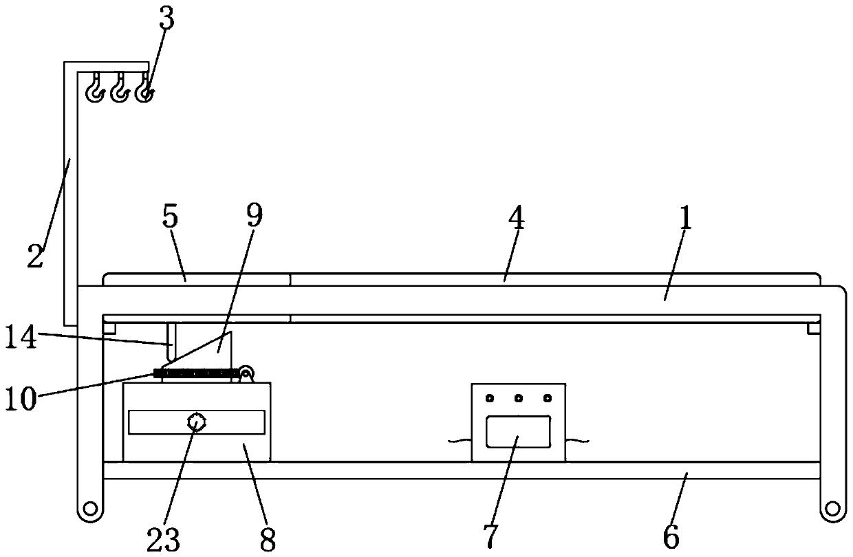
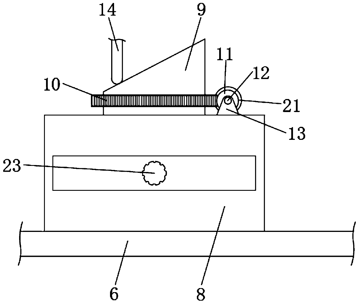
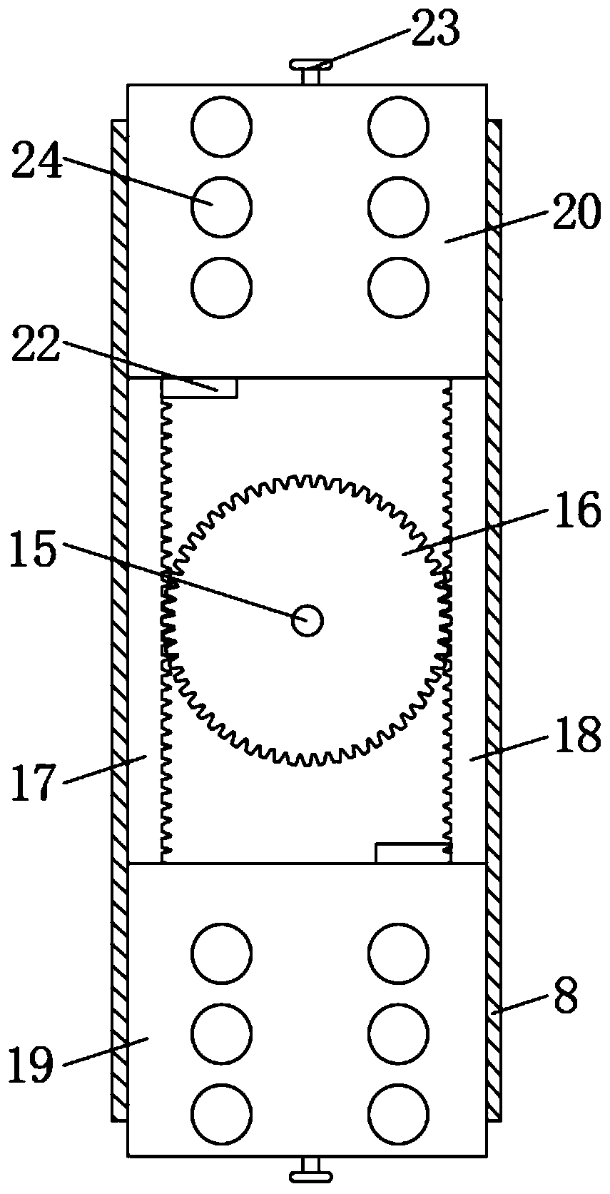
[0022] see Figure 1 to Figure 3 , the present invention provides a technical solution: an ICU intensive care equipment, including a bed frame 1, through which the bed frame 1 provides support for the bed board 4 and the back board 5, and the left side of the bed frame 1 is fixedly connected with a support rod 2, which supports The surface near the top of the rod 2 is fixedly connected with a hook 3, and the hanging water injected by the patient every day is h...


PUM


Abstract

The invention discloses an intensive care device for ICUs (Intensive Care Unit), which comprises a bedstead, a supporting pole is fixedly connected to the left side of the bedstead, hooks are fixedlyconnected to the surface, which is close to the top, of the supporting pole, a bed board is fixedly connected to the internal wall, which is closed to the top, of the bedstead, a back board is turnably connected to the left side of the bed board through a shaft, the surface of the back board is movably connected to the internal wall of the bedstead, and a bottom board is fixedly connected to the surface, which is close to the bottom, of the bedstead. Through the cooperation between the structures, the invention solves the following problems: in the process of actual use, because a patient lieson the bed for a long time, local compression can easily lead to blood circulation disorder, bringing discomfort to the patient, moreover, the conventional bed can hardly be adjusted to multiple angles, and as a result, more comfortable sitting and lying experience can hardly be brought to the patient; and furthermore, because the conventional bed can hardly support various monitoring devices aswell, detection devices cannot be conveniently carried as the patient is moved, bringing inconvenience to the monitoring of the patient.

Description

technical field [0001] The invention relates to the technical field of medical equipment, in particular to an ICU intensive care equipment. Background technique [0002] Intensive care (intensive care) refers to the use of various advanced medical technologies, modern monitoring and rescue equipment to implement intensive intensive treatment and nursing care for all kinds of critically ill patients. In order to ensure the patient's survival and subsequent quality of life to the greatest extent, the comprehensive intensive care unit is generally located in the center of the hospital, close to the anesthesiology department and various operating departments, and the intensive care unit of each specialty is located in each specialty In the ward. Generally, it tends to be a large ward, and the room is often divided into semi-closed units by large flat transparent glass. The ward is spacious, with a clean area and a non-clean area, where various medicines, medical instruments an...

Claims


Application Information

Patent Timeline
Patent Type & Authority Applications(China)
IPC IPC(8): A61G7/10A61G7/005A61G7/05A61B5/00A61M5/14
Inventor 吕桂荣
Owner 吕桂荣
Why Eureka
Try Eureka