Organ type check accelerating specimen frame
An organ-like, specimen-based technology, applied in the field of check racks, can solve problems such as medical errors, cumbersome operation steps, and specimen confusion, and achieve the effect of reasonable check angle, simple operation mode, and avoiding secondary pollution
- Summary
- Abstract
- Description
- Claims
- Application Information
AI Technical Summary
Problems solved by technology
Method used
Image
Examples
specific Embodiment approach 1
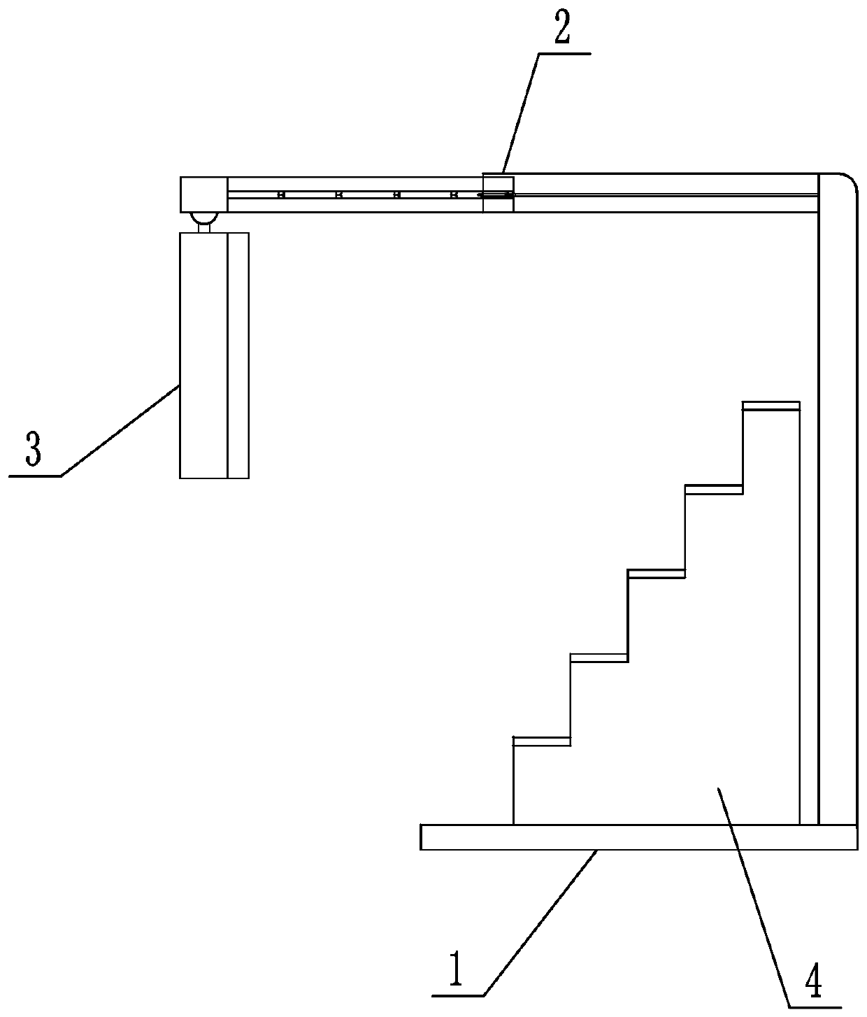
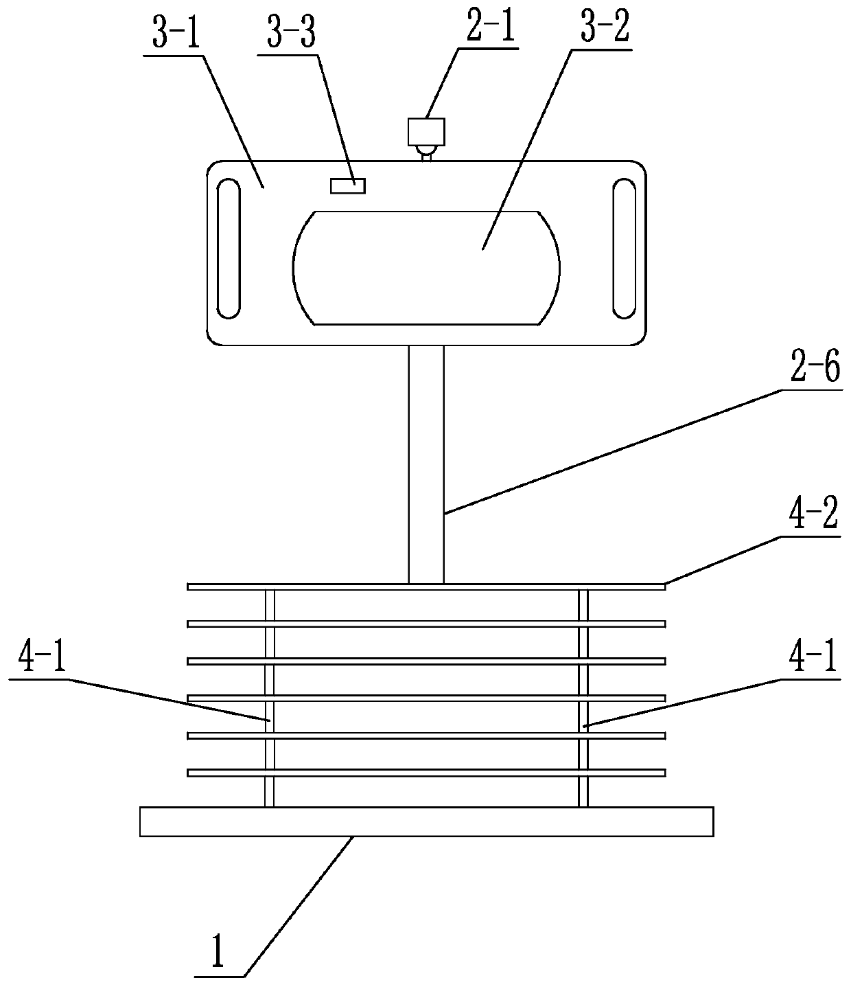
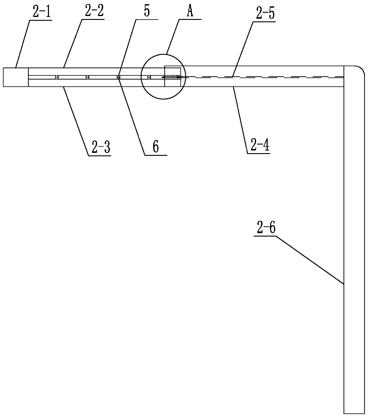
[0032] Specific implementation mode one: as figure 1 , figure 2 , image 3 , Figure 4 , Figure 5 , Figure 6 , Figure 7 , Figure 8 , Figure 9 and Figure 10 As shown, this embodiment includes a base plate 1, an adjustment rod 2, an inspection window 3 and a ladder frame 4, the base plate 1 is arranged horizontally, the ladder frame 4 is arranged on the base plate 1, and one end of the adjustment rod 2 is arranged on the base plate 1. The other end of the rod 2 is hinged with an inspection window 3, and the inspection window 3 is arranged toward the ladder frame 4. The adjustment rod 2 includes a connector 2-1, an upper sliding rod 2-2, a lower sliding rod 2-3, a sliding sleeve 2-4, Partition plate 2-5 and vertical rod 2-6, the top of the inspection window 3 is hinged to the connector 2-1, and the upper sliding rod 2-2 and the lower sliding rod 2-3 are horizontally arranged on the connector 2 -1 and the sliding sleeve 2-4, the sliding sleeve 2-4 is connected with...
specific Embodiment approach 2
[0044] Specific implementation mode two: as figure 2 , image 3 , Figure 4 , Figure 5 , Figure 6 , Figure 7 , Figure 8 , Figure 9 and Figure 10 As shown, the lower end of the vertical bar 2-6 and the bottom plate 1 are hinged through a damping shaft, so that the angle between the lower end of the vertical bar 2-6 and the bottom plate 1 is adjustable, and can stay at any angle. External force can change the original position between the lower end of vertical bar 2-6 and base plate 1 again. The upper end of the vertical rod 2-6 and the sliding sleeve 2-4 are hinged through another damping shaft, so that the angle between the upper end of the vertical rod 2-6 and the sliding sleeve 2-4 can be adjusted, and can only be changed again by applying an external force. The original position between the lower end of vertical bar 2-6 and sliding sleeve 2-4.
specific Embodiment approach 3
[0045] Specific Embodiment 3: This embodiment is a further limitation of Specific Embodiment 1 or 2. Another way to form the ladder shape is that the ladder shape is composed of multiple transverse cutting lines and multiple vertical oblique cutting lines alternately, thus forming multiple The inclined setting of the top plate 4-2 is more conducive to the fitting of the specimen rack on the ladder frame 4, and is conducive to providing a convenient viewing angle.
[0046] work process:
[0047] Place the specimen racks one by one on each top plate 4-2 of the ladder frame 4 from bottom to top. Multiple specimen racks can be placed on one top plate 4-2, and hold the hands on the support frame through the two long holes 3-6 respectively. 3-1 at both ends, push the support frame 3-1 hard, so that the upper sliding rod 2-2 and the lower sliding rod 2-3 are inserted into the sliding sleeve 2-4 at the same time, and the closest sliding rod on the upper sliding rod 2-2 The upper magn...
PUM
 Abstract
Description
Claims
Application Information
 - R&D Engineer
- R&D Manager
- IP Professional
- Industry Leading Data Capabilities
- Powerful AI technology
- Patent DNA Extraction
Browse by: Latest US Patents, China's latest patents, Technical Efficacy Thesaurus, Application Domain, Technology Topic, Popular Technical Reports.
© 2024 PatSnap. All rights reserved.Legal|Privacy policy|Modern Slavery Act Transparency Statement|Sitemap|About US| Contact US: help@patsnap.com


