Environment-friendly solid garbage treatment equipment

A technology for solid waste and processing equipment, applied in grain processing, solid waste removal, etc., can solve problems such as low pulverization efficiency, achieve the effect of convenient collection and avoid dust pollution

Active Publication Date: 2019-05-28
上海碳澜环境集团有限公司
View PDF13 Cites 2 Cited by
  • Summary
  • Abstract
  • Description
  • Claims
  • Application Information

AI Technical Summary

Problems solved by technology

[0004] The purpose of the present invention is to provide an environment-friendly solid waste treatment equipment, which has the advantage of high crushing efficiency and solves the problem of low crushing efficiency of common environment-friendly solid waste treatment equipment

Method used


Image

  • Environment-friendly solid garbage treatment equipment
  • Environment-friendly solid garbage treatment equipment
  • Environment-friendly solid garbage treatment equipment

Examples


no. 1 approach

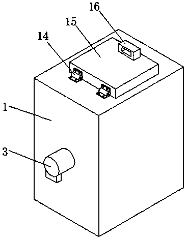
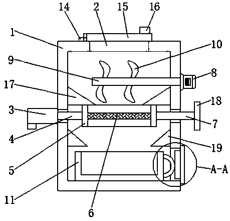
[0023] First implementation: see Figure 1-4 , an environment-friendly solid waste treatment equipment, comprising a housing 1, the top of the housing 1 is provided with a feeding port 2, the top of the housing 1 and the position corresponding to the feeding port 2 are movably connected with a cover plate 15 through a hinge 14, through Setting the cover plate 15 can close the device to avoid dust pollution caused by the device during work. The right side of the top of the cover plate 15 is fixedly connected with an operating handle 16. By setting the operating handle 16, the staff can operate the cover plate 15. More convenient, the electric push rod 3 is fixedly connected to the midpoint on the left side of the housing 1, and the power rod 4 is fixedly connected to the output end of the electric push rod 3, and the right side of the power rod 4 runs through the housing 1 and extends to its interior for fixing. The shaking frame 5 is connected, and the left and right sides of ...

no. 2 approach

[0026] The second embodiment: as shown in claim 1, an environment-friendly solid waste treatment equipment includes a casing 1, the top of the casing 1 is provided with a feeding port 2, and the middle point on the left side of the casing 1 is The electric push rod 3 is fixedly connected to the output end of the electric push rod 3, and a power rod 4 is fixedly connected to the output end of the electric push rod 3. The right side of the power rod 4 runs through the housing 1 and extends to its interior to be fixedly connected to a shaking frame 5, so The left and right sides of the inner wall of the housing 1 and the position corresponding to the shaking frame 5 are fixedly connected with a material guide plate 17, the inner wall of the shaking frame 5 is fixedly connected with a screen 6, and the right side of the shaking frame 5 is fixedly connected with a Connecting rod 7, the right side of the connecting rod 7 runs through the housing 1 and extends to the outside, the top ...


PUM


Abstract

The invention discloses environment-friendly solid garbage treatment equipment. A shell is included. A charging port is formed in the top of the shell. An electric push rod is fixedly connected to themiddle point position of the left side of the shell. A power rod is fixedly connected to the output end of the electric push rod. The right side of the power rod penetrates through the shell and extends into the shell to be fixedly connected with a swinging frame. The inner wall of the swinging frame is fixedly connected with a screen. Through mutual cooperation of the shell, the charging port, the electric push rod, the power rod, the swinging frame, the screen, a connecting rod, a pulverizing motor, a pulverizing shaft, pulverizing teeth, a collecting frame, a discharging port and a stop door, the environment-friendly solid garbage treatment equipment high in pulverizing efficiency is achieved; the charged garbage can be thoroughly pulverized; firstly, pulverized fine garbage falls downthrough the screen while large solid garbage is continuously pulverized till pulverizing is thorough, and therefore inconvenience caused by repeated charging is avoided.

Description

technical field [0001] The invention relates to the technical field of garbage treatment, in particular to an environment-friendly solid garbage treatment equipment. Background technique [0002] Garbage is solid waste generated in human daily life and production. Due to the large amount of discharge, complex and diverse components, and polluting, resourceful and social nature, it needs harmless, resourceful, reduction and socialized treatment. If it is not handled properly, it will pollute the environment, affect environmental sanitation, waste resources, destroy the safety of production and life, and disrupt social harmony. Garbage disposal is to quickly remove garbage, conduct harmless treatment, and finally make reasonable use of it. Applied waste disposal methods are sanitary landfill, high-temperature composting and incineration, and the purpose of waste disposal is harmlessness, resource utilization and reduction. [0003] Nowadays, with the continuous improvement of...

Claims


Application Information

Patent Timeline
Patent Type & Authority Applications(China)
IPC IPC(8): B02C18/14B02C18/16B02C18/18B02C18/24B02C18/22B02C23/16B02C23/18B09B3/00
Inventor 来洒洒
Owner 上海碳澜环境集团有限公司
Why Eureka
Try Eureka