Selective laser melting system, gas circulating device and printing method

A technology of laser melting and gas circulation, which is applied in the direction of improving process efficiency and energy efficiency, can solve the problems of long oxygen removal time and insufficient oxygen removal, and achieve the goal of realizing repeated use, improving printing efficiency and reducing oxygen removal the effect of time

Active Publication Date: 2019-05-28
HANS LASER TECH IND GRP CO LTD
View PDF6 Cites 3 Cited by
  • Summary
  • Abstract
  • Description
  • Claims
  • Application Information

AI Technical Summary

Problems solved by technology

[0006] In order to solve the above problems, an embodiment of the present invention provides a selective laser melting system to solve the problem of insufficient oxygen removal or too long oxygen removal time in the selective laser melting system in the prior art

Method used


Image

  • Selective laser melting system, gas circulating device and printing method
  • Selective laser melting system, gas circulating device and printing method
  • Selective laser melting system, gas circulating device and printing method

Examples


Embodiment 1

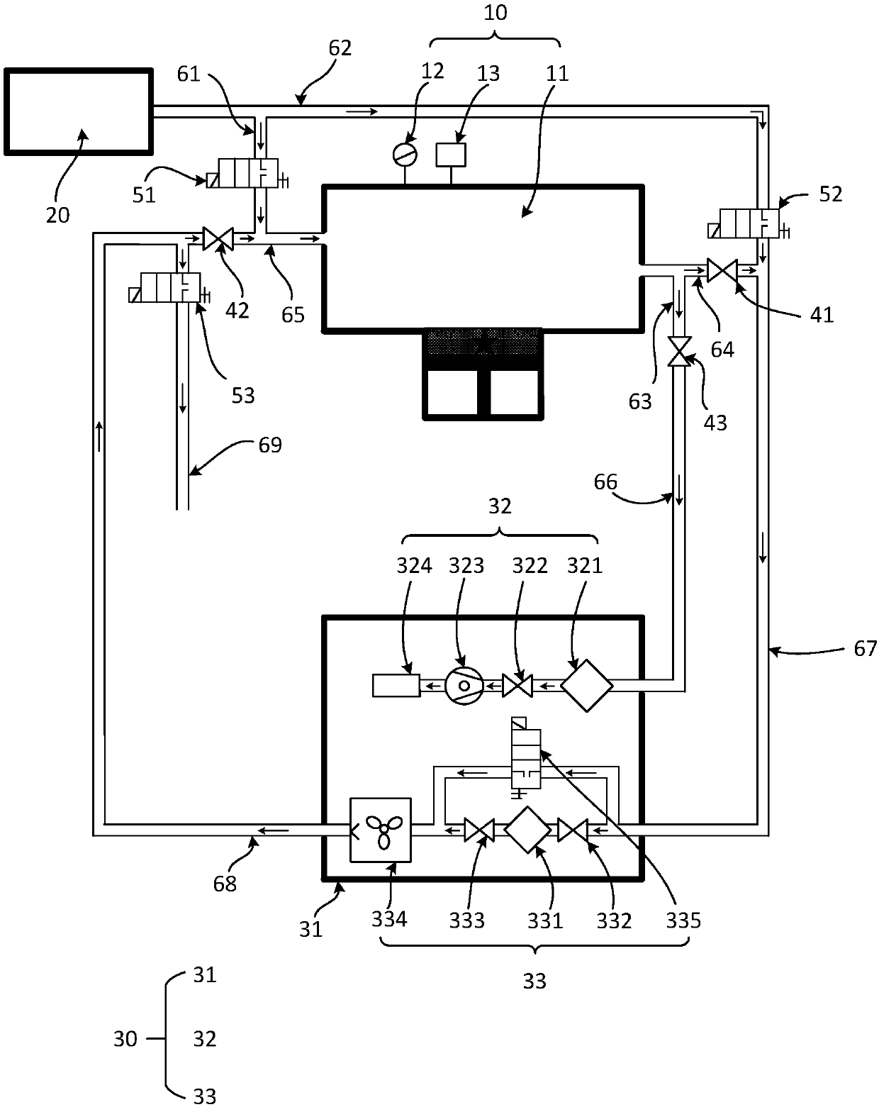
[0055] refer to figure 1 , shows a structural block diagram of an alternative scheme of the selective laser melting system provided by the embodiment of the present invention, the system includes a selective laser melting device 10, a protective gas output device 20 and a gas circulation device 30, wherein the selective laser melting The melting device 10 includes a forming chamber 11, a pressure gauge 12 and an oxygen transmitter 13 arranged on the wall of the forming chamber 11; the gas circulation device 30 includes a casing 31 and a vacuum assembly 32 arranged in the inner cavity of the casing 31 And a gas circulation filter assembly 33, the protective gas output device 20 is used to deliver protective gas to the selective laser melting equipment 10 and the gas circulation device 30, wherein the protective gas is helium or an inert gas, such as argon;

[0056] The forming cavity 11 and the gas circulation filter assembly 33 form the first gas path, the protective gas outpu...

Embodiment 2

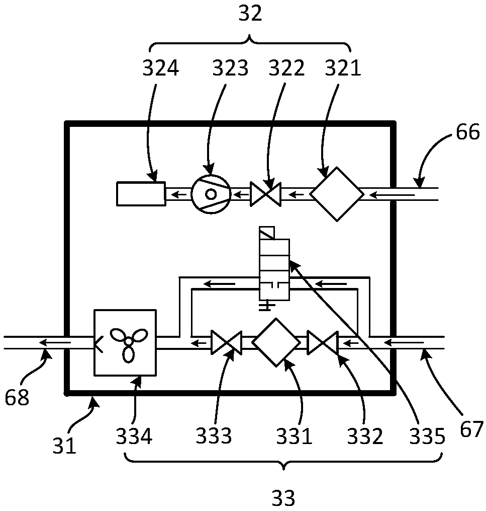
[0107] An embodiment of the present invention provides a gas circulation device, which is applied to the selective laser melting system of Embodiment 1, see image 3 , which shows a schematic structural view of the gas circulation device provided by the embodiment of the present invention. The gas circulation device includes a housing 31 and a vacuum assembly 32 and a gas circulation filter assembly 33 arranged in the inner cavity of the housing 31. The vacuum assembly 32 is connected to Vacuum the intake pipe 66, and the gas circulation filter assembly 33 is connected to the filter intake pipe 67 and the filter air pipe 68, wherein:

[0108] The gas circulation filter assembly 33 is used to purify the air in the forming cavity 11 and related pipelines in the selective laser melting system, which includes a first filter 331, a fourth vacuum damper valve 332, a fifth vacuum damper valve 333, a gas cycle power unit 334 and a fourth electromagnetic valve 335;

[0109] The fourth...

Embodiment 3

[0123] The embodiment of the present invention also provides a printing method, which is applied to the selective laser melting system of the first embodiment above. In this embodiment, it is assumed that all gas circuit switches in the selective laser melting system are initially closed, as Figure 5 As shown in the flow chart, the method includes:

[0124] S1. Keep the gas path switch in the first gas path, the gas path switch between the protective gas output device and the forming cavity in the second gas path closed, and turn on the gas between the vacuum component and the forming cavity in the second gas path. circuit switch, the gas circuit switch in the third gas circuit;

[0125]S2. Start the protective gas output device, deoxygenate the third gas path, and start the vacuuming component to vacuumize the forming cavity;

[0126] S3. The pressure gauge detects whether the air pressure in the forming cavity reaches the preset air pressure range, if not, continue to exec...


PUM


Abstract

The invention belongs to the technical field of additive manufacturing equipment, and relates to a selective laser melting system. The selective laser melting system comprises selective laser meltingequipment, a protective gas output device and a gas circulating device, wherein the selective laser melting equipment comprises a forming cavity, a pressure meter and an oxygen transmitter; the gas circulating device comprises a shell, a vacuumizing assembly and a gas circulating filtering assembly; the forming cavity and the gas circulating filtering assembly forms a first gas path, the protective gas output device, the forming cavity and the vacuumizing assembly form a second gas path, the protective gas output device and the gas circulating filter assembly form a third gas path, each gas path comprises a plurality of connecting pieces, and the first gas path, the second gas path and the third gas path are interconnected through a common part of the connecting pieces. According to the selective laser melting system, the oxygen removal efficiency in the forming material inside the forming cavity can be improved, and the overall oxygen removal speed is accelerated; in addition, the invention further provides a gas circulating device and a printing method applied to the system

Description

technical field [0001] Embodiments of the present invention belong to the technical field of additive manufacturing equipment, and in particular relate to a selective laser melting system, a gas circulation device and a printing method applied to the selective laser melting system. Background technique [0002] Selective Laser Melting (SLM) is widely used in existing additive manufacturing equipment. SLM is an additive manufacturing technology for direct forming of metal parts. This technology is based on the CAD model, using laser focus to gradually melt the formed material. Additive manufacturing method of layer cladding accumulation, in which the temperature in the forming cavity, oxygen concentration, and the speed at which the protective gas flows over the surface of the forming material (especially metal powder and plastic powder) all have an impact on the quality of the printed product, such as, When printing without the protection of protective gas, the elements such...

Claims


Application Information

Patent Timeline
Patent Type & Authority Applications(China)
IPC IPC(8): B22F3/105
CPCY02P10/25
Inventor 王先礼喻鹏袁剑吕启涛高云峰
Owner HANS LASER TECH IND GRP CO LTD
Why Eureka
Try Eureka