Power control device for low-power laser device and control method thereof

A power control and laser technology, applied in the field of lasers, can solve problems such as inapplicability and damage to objects, and achieve the effects of convenient control, increased service life, and reduced corrosion

Active Publication Date: 2019-05-28
山东铭肯机械制造有限公司
View PDF6 Cites 0 Cited by
  • Summary
  • Abstract
  • Description
  • Claims
  • Application Information

AI Technical Summary

Problems solved by technology

[0004] The above invention effectively solves the power adjustment of high-speed lasers, but when this invention is applied to low-power lasers, by increasing the current to control the low-power lasers, it is easy to reach the threshold of the power level of the low-power lasers and reach the threshold of the low-power lasers. After the threshold of the power level, t

Method used


Image

  • Power control device for low-power laser device and control method thereof
  • Power control device for low-power laser device and control method thereof
  • Power control device for low-power laser device and control method thereof

Examples


Embodiment 1

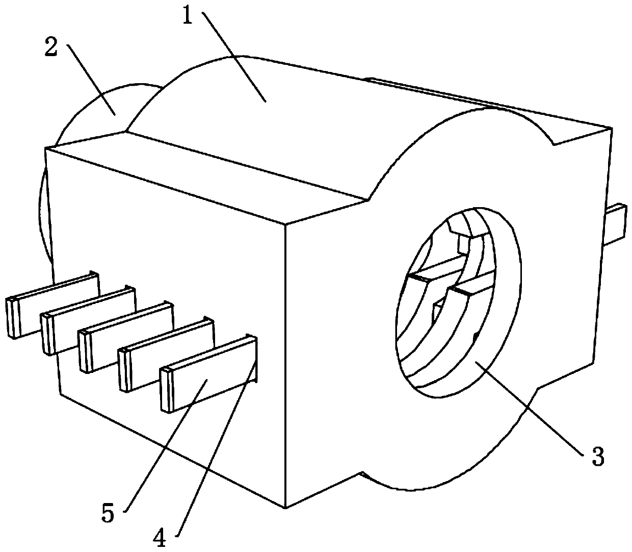
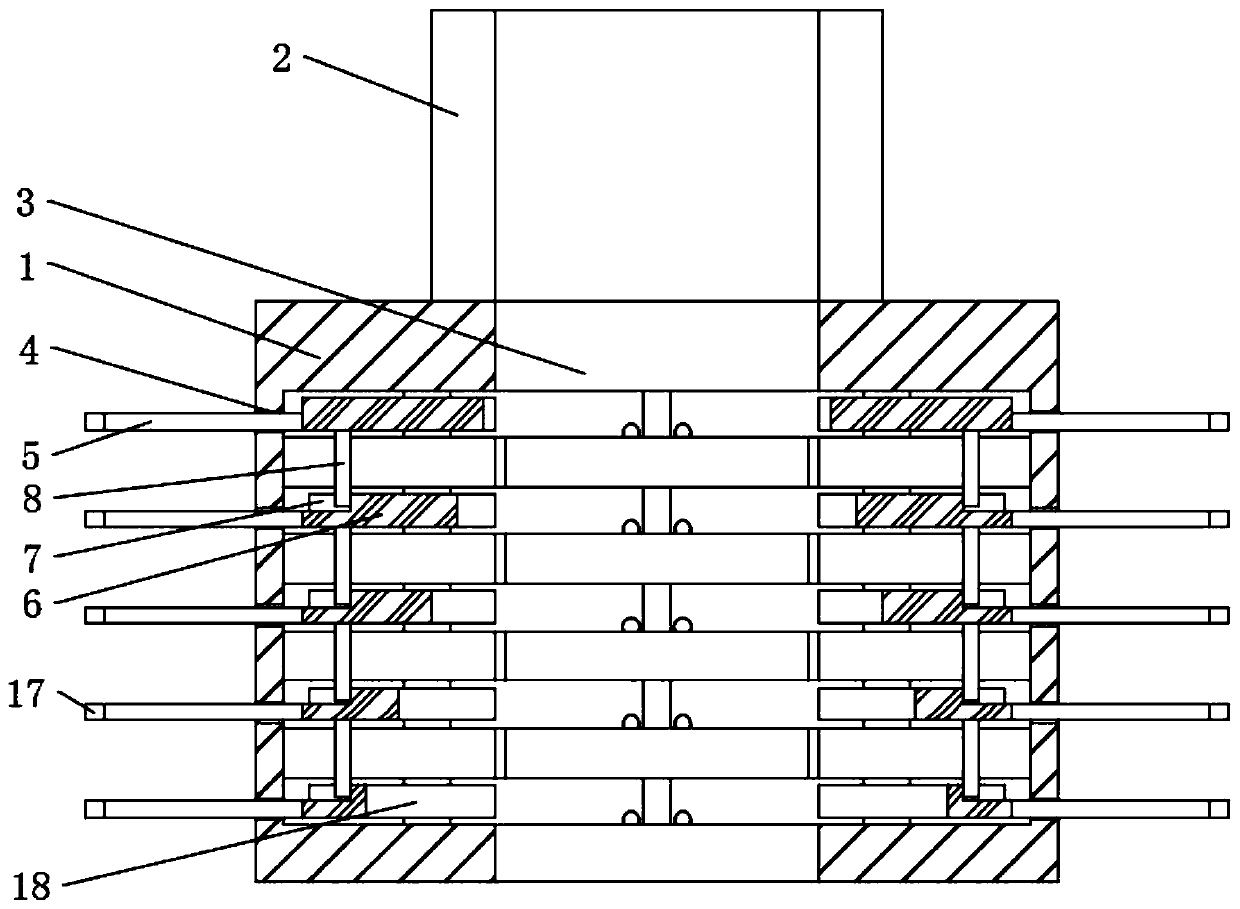
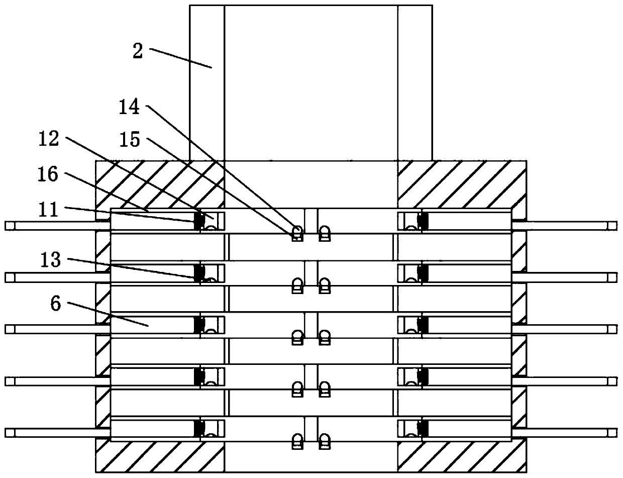
[0048] A kind of laser power control device and method thereof for low power application, please refer to figure 1 , including a laser control lens 1, the rear end of the laser control lens 1 is fixedly connected with a laser guide 2, and the outer end of the laser guide 2 is fixedly connected with a laser emitter, and the laser emitter emits laser light into the laser guide 2, so that the laser passes through The laser guide 2 and the laser control lens 1 act on the outer end of the object, so that the laser can act on the object. There are a plurality of sliding holes 4 drilled at the left and right ends of the laser control lens 1. Please refer to Figure 2-3 , the walls of the left and right ends of the guide groove 3 are dug with a plurality of chutes 16, and the left and right ends of the plurality of chutes 16 are slidably connected with a laser diameter control block 6, and the laser diameter control blocks 6 at the left and right ends are all dug with a semi-arc shape....

Embodiment 2

[0052] The present invention is in the operation step to the power control of low-power laser:

[0053] Step 1. Connect the laser guide 2 with the laser emitter, and turn on the current detector, power controller, power supply and laser emitter respectively, so that the laser emitter can emit the laser beam.

[0054] Step 2: The staff adjusts the diameter of the laser beam according to the power of the laser beam required to act on the object.

[0055] Step 3, please refer to image 3 , the staff will move the adjustment block 5 to the end close to the guide groove 3, and drive the laser diameter control block 6 to move to the end close to the guide groove 3. Under the mutual cooperation between the groove 13 and the hemispherical block 14, the laser diameter The position of the control block 6 is fixed so that the laser diameter control block 6 blocks the laser beam emitted by the laser emitter.

[0056] Step 4: The staff acts on the object with the laser beam after the pow...


PUM

PropertyMeasurementUnit
Sizeaaaaaaaaaa

Abstract

The invention discloses a power control device for a low-power laser device and a control method of the power control device for the low-power laser device and belongs to the field of laser devices. The power control device for the low-power laser device comprises a laser device control lens. A laser guide device is fixedly connected to the back end of the laser device control lens. The outer endof the laser guide device is fixedly connected with a laser emitter. In the prior art, through cooperation of a convex lens and a concave lens in a beam expander, the diameter of a laser is changed, the manner only can change the output power of the laser of a unit area and cannot change the total power acting on an object, and the direction of the laser beam can be changed. Compared with the prior art, the power control device for the low-power laser device keeps the output power of the laser of the unit area constant, changes the diameter of the laser and influences the total power of the laser acting on the object at the same time, and adjustment of the power of the laser acting on the object is achieved.

Description

technical field [0001] The invention relates to the field of lasers, more specifically, to a laser power control device for low-power applications and a method thereof. Background technique [0002] Existing lasers can be divided into: first-class lasers, second-class lasers, third-class lasers, and fourth-class lasers according to their different powers. 1. First-class lasers: harmless and control-free lasers. The laser light emitted by this level of laser has no danger to the human body during use, and it will not damage the eyes even if you look directly at it. No control is required for this type of laser; 2. Second-level laser: a low-power laser. Although the output laser power is low, it will not cause eye damage if you look at it occasionally with your eyes, but you should not look directly at the laser beam for a long time. Otherwise, the fundus cells are damaged by photons and damage the retina. However, this type of laser has no thermal damage to human skin; 3....

Claims


Application Information

Patent Timeline
IPC IPC(8): B23K26/064B23K26/38B23K26/70G05B19/18
Inventor 赵帅
Owner 山东铭肯机械制造有限公司
Why Eureka
Try Eureka