
Single-stroke acting chain transmission wave energy conversion device

A conversion device and wave energy technology, applied in ocean energy power generation, engine components, machines/engines, etc., can solve the problems of unstable up and down movement of oscillating floats, aggravated wear, and equipment performance degradation, and achieve enhanced resistance to typhoons and harsh sea conditions. The ability to improve the stress condition, the effect of stability improvement

Pending Publication Date: 2019-05-28
闻福三
View PDF2 Cites 3 Cited by
  • Summary
  • Abstract
  • Description
  • Claims
  • Application Information

AI Technical Summary

Problems solved by technology

[0006] The shortcomings of the above-mentioned prior art are summarized as follows: 1. Due to the two tight sides acting on the reversing wheel at the same time, the load is too large and the wear is aggravated; The up and down movement of the oscillating float is unstable; 3. Due to the small number of meshing teeth of the sprocket chain, it causes poor stress and tooth loss, resulting in many faults and difficult maintenance; 4. Due to the large diameter of the column, the resistance to waves is still very large. Therefore, the wave energy conversion efficiency is reduced; the above-mentioned many factors lead to the weakening of the wind and wave resistance and low conversion efficiency of the entire power generation device, and the overall equipment performance declines

Method used


Image

  • Single-stroke acting chain transmission wave energy conversion device
  • Single-stroke acting chain transmission wave energy conversion device
  • Single-stroke acting chain transmission wave energy conversion device

Examples


Embodiment Construction

[0037] The present invention will be described below in conjunction with the accompanying drawings and examples.

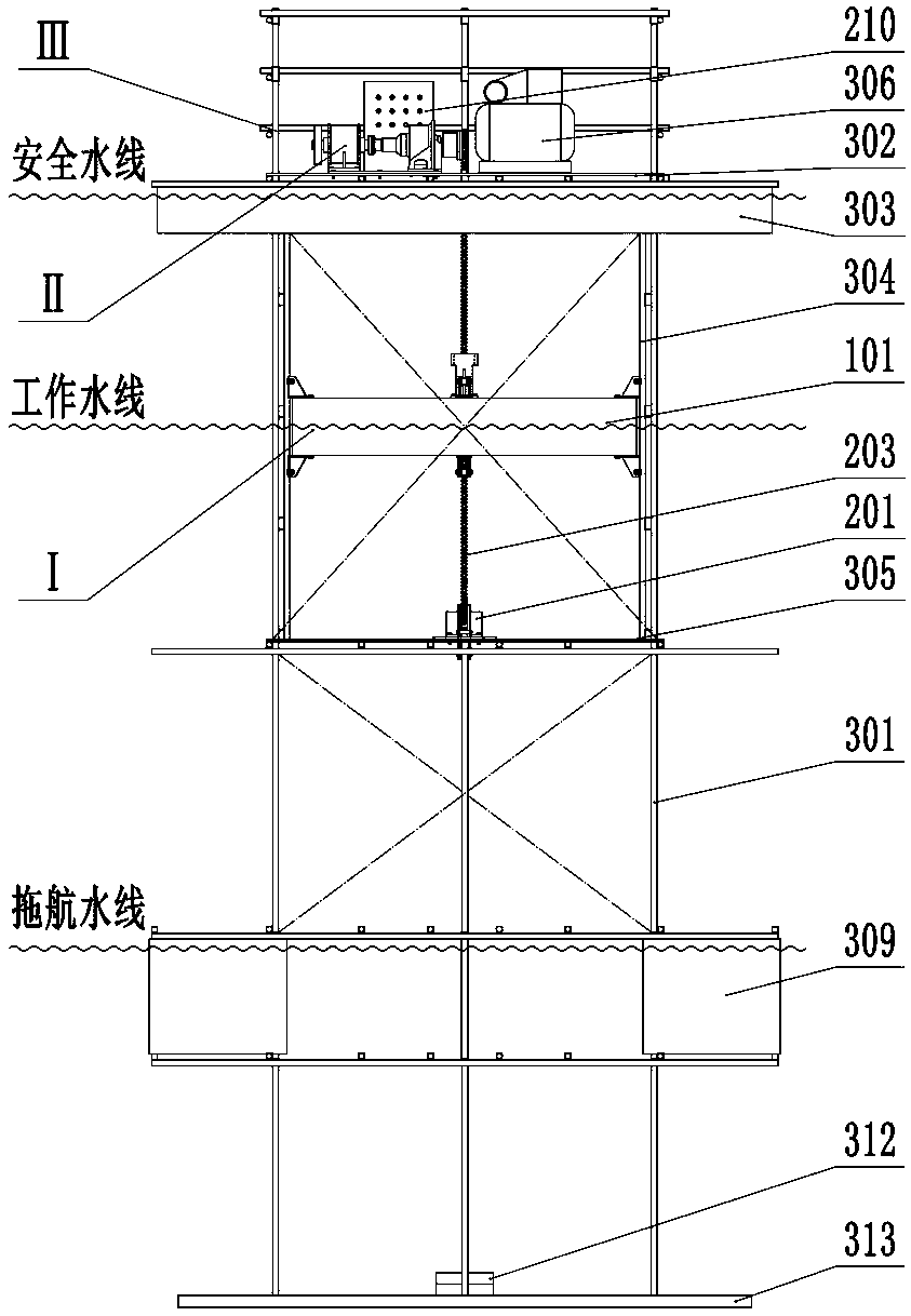
[0038] like figure 1 As shown, the chain-driven wave energy conversion device of this embodiment is a power generation device floating on the sea. It is characterized in that the oscillating buoy with the guide bar 304 of the floating frame as the moving track is located in the water below the truss upper platform 302 of the floating frame, and the mechanical energy-electric energy conversion device is located on the truss upper platform 302 of the floating frame .

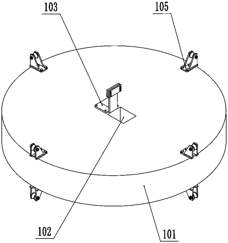
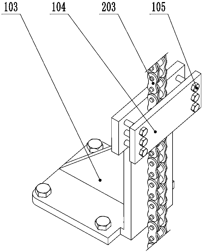
[0039] like Figure 2-5 As shown, the oscillating float is composed of a wave-absorbing floating body 101, a chain fixing device and a guiding device; and electric control box 210; as Figure 7 As shown, the floating frame is composed of a truss main body 301 built into a grid structure with rods, a truss upper platform 302, a safety floating body 303, a guide rod 304 matched with the guide devic...


PUM


Abstract

The invention discloses a single-stroke acting chain transmission wave energy conversion device which comprises an oscillating float, a mechanical energy-electric energy conversion device and a floating machine frame. The oscillating float comprises a wave absorbing floating body, a chain fixing device and a guiding device, the mechanical energy-electric energy conversion device comprises a chaintransmission device, a speed-increasing transmission, a one-way coupler, a power generator, a flywheel and an electric control box, the floating machine frame includes a truss main body built by rods,a truss upper platform, a safety floating body, a guide rod, a truss lower platform, a lifting system and a damping counterweight system, the chain transmission device comprises a chain penetrating through the wave absorbing floating body, a load sprocket, a reversing sprocket and a chain tensioning device, one side of the chain is fixed to the oscillating float and transfers and outputs the kinetic energy of the wave absorbing floating body, and the lifting system includes an air compressor, a check valve, a two-position three-way valve, a safety shut-off valve, a lifting pontoon and a connecting pipeline. The floating energy conversion device is simple in structure, stable and reliable, can be lifted and lowered, can resist strong wind and waves, and has the high wave energy utilizationrate.

Description

technical field [0001] The invention relates to an energy conversion device, in particular to an energy conversion device utilizing ocean wave energy, in particular to a single-stroke work chain drive wave energy conversion device. Background technique [0002] The wave energy is absorbed by the oscillating buoy floating on the water surface, and then the wave energy is converted into mechanical energy through the transmission chain or belt connected to the floating body. The conversion efficiency is high, simple and reliable, and it has been applied; the existing chain transmission There are still some problems in the wave energy conversion device, which need to be improved and perfected. [0003] 1. Chinese invention patent application publication specification CN 101460733 A, international publication WO2007 / 139395 English. 2007.12.6 discloses a device for converting wave energy; Figure 11 As shown (this figure is extracted from the CN 101460733 A specification), the low...

Claims


Application Information

Patent Timeline
IPC IPC(8): F03B13/18F03B13/20
CPCY02E10/30
Inventor 闻福三李政清任齐伍时和赵京明郭海智李伟杨泽华葛泽波符永福孙塑埴窦明成王标极朱承峰
Owner 闻福三
Learn More