
Device and method for measuring surface tension coefficient

A technology of surface tension coefficient and measuring device, applied in the field of physical quantity measurement, can solve problems such as low precision, influence of surface tension, inability to effectively determine and measure the absolute position of the rising height and boundary light, and avoid systematic errors and eliminate contact angles. the effect of

Pending Publication Date: 2019-05-28
SHAANXI UNIV OF SCI & TECH
View PDF0 Cites 0 Cited by
  • Summary
  • Abstract
  • Description
  • Claims
  • Application Information

AI Technical Summary

Problems solved by technology

[0002] The determination of the surface tension coefficient of a liquid is of great significance to the study of the properties of objects. Traditional measurement methods generally have the characteristics of complex operation, slow speed, and low precision; The reflection method is relatively simple to operate and has relatively high precision; however, the maximum height of the liquid rise needs to be measured in the plate insertion method, and the absolute position of the boundary light needs to be determined when the laser reflection method is used, and the plate must be strictly perpendicular to the horizontal plane; and the rise height of the liquid and The absolute position of the boundary light cannot be effectively determined and measured, which has a certain impact on the surface tension of the final measurement. At the same time, it cannot be measured when the plate has a certain inclination angle.

Method used


Image

  • Device and method for measuring surface tension coefficient
  • Device and method for measuring surface tension coefficient
  • Device and method for measuring surface tension coefficient

Examples


Embodiment Construction

[0035] The present invention will be further explained below in conjunction with the accompanying drawings and specific embodiments.

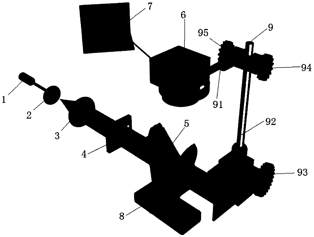
[0036] Reference attached figure 1 As shown, a surface tension coefficient measuring device of the present invention includes a light source 1, a beam expander 2, a convex lens 3, a slit stop 4, a half mirror 5, a linear array CCD 6, a computer 7, a flat panel 8 and a support 9 ;

[0037] The light source 1 adopts a laser, and the light source 1 is used to generate a light beam, and the light beam is a parallel light beam; the light source 1 emits a Gaussian beam and passes through a beam expander 2 and a convex lens 3 on the path to form a collimated and parallel light beam and then irradiates it on the slit diaphragm 4; A slit diaphragm 4 is arranged on the parallel light path, and the position of the incident light on the curved liquid surface is controlled by using the slit diaphragm 4 to control the boundary of the parallel light rays; A...


PUM


Abstract

The invention discloses a device and method for measuring the surface tension coefficient. The device comprises a light source, a slit diaphragm, a semi-transparent semi-reflective mirror, a linear array CCD and a flat plate. Aligned parallel light beams pass through the semi-transparent semi-reflective mirror to vertically irradiate the bent liquid surface near the flat plate after the edges of the light beams are adjusted through the slit diaphragm; the linear array CCD collects light signals reflected by the bent liquid surface, converts the light signals into data and transmits the data toa computer. The bent liquid surface is scanned by laser beams by controlling the edges of the light beams through the slit diaphragm, the variation, caused by the different detection distances, of the relative positions of the edges of the reflection light field is obtained to determine the liquid surface slope, and the surface tension coefficient is obtained by measuring the relative variation amount and corresponding liquid surface slope of the incident light beam boundary light position in combination with the analysis relation. The complete relative measurement is adopted for the measuring device, the influences of contact angles are eliminated theoretically, the system errors are effectively avoided, and meanwhile the device has the advantages of having real-time performance and being free of damage and contact.

Description

technical field [0001] The invention relates to the technical field of physical quantity measurement, in particular to a surface tension coefficient measuring device and a measuring method thereof. Background technique [0002] The determination of the surface tension coefficient of a liquid is of great significance to the study of the properties of objects. Traditional measurement methods generally have the characteristics of complex operation, slow speed, and low precision; The reflection method is relatively simple to operate and has relatively high precision; however, the maximum height of the liquid rise needs to be measured in the plate insertion method, and the absolute position of the boundary light needs to be determined when the laser reflection method is used, and the plate must be strictly perpendicular to the horizontal plane; and the rise height of the liquid and The absolute position of the boundary light cannot be effectively determined and measured, which ha...

Claims


Application Information

Patent Timeline
Patent Type & Authority Applications(China)
IPC IPC(8): G01N13/02
Inventor 罗道斌骞来来师博秦毅盼岳宗敏
Owner SHAANXI UNIV OF SCI & TECH
Learn More