Toroidal trolley for fusion fission cladding refueling system

A trolley and hoop technology, applied in the direction of transportation and packaging, reactor fuel elements, conveyors, etc., can solve the problems of complex refueling operations, increased refueling time, and low heat exchange efficiency of cladding modules

Pending Publication Date: 2019-05-28
INST OF NUCLEAR PHYSICS & CHEM CHINA ACADEMY OF
4 Cites 1 Cited by

AI-Extracted Technical Summary

Problems solved by technology

In the 1970s and 1980s, the United States, Japan, and Turkey conducted a lot of research work on hybrid reactors. Fusion drive methods include magnetic mirrors, tokamak magnetic confinement, and laser inertial confinement. fissile uranium/thorium cladding, but neither goes beyond simple conceptual studies
The cladding is composed of many miniature pressure shells and welded, which makes the assembly workload very large and the reliability is reduced; the manifold of the entire cladding...

Method used

A, hoop dolly 4 is installed on radial dolly 3, cladding module 3 is installed on hoop dolly, and the hydraulic cylinder on hoop dolly jacks up cladding module, avoids cladding module and ground Contact, the ring is installed on the trolley with a positioning bump of a corresponding length;
Described radial track 1 comprises radially lower track 101 and radially upper track 107 installed along ring track 2 radial direction, because cladding module is longitudinally installed on ring car 4, therefore needs two up and down track, so as to ensure the safety of the cladding module installed, and can improve the moving speed of the trolley, the radial upper track 107 is installed above the radial lower track 101 by a bracket; the radial lower track 101 includes at least two tracks, thereby ensuring The radial trolley moves reliably on the ra...

Abstract

The invention discloses a toroidal trolley for a fusion fission cladding refueling system. The toroidal trolley comprises an E-shaped frame body, hydraulic cylinders and rolling wheel sets. The framebody is fan-shaped, at least two rows of rolling wheel sets capable of moving in the same direction are mounted at the bottom of the frame body, and at least two rows of hydraulic cylinders are mounted on the top surface of the frame body. The toroidal trolley can facilitate transport of a fusion fission cladding module and refuel the fusion fission cladding system.

Application Domain

Nuclear energy generationReactor fuel elements +1

Technology Topic

Vehicle frameAerospace engineering +2

Image

  • Toroidal trolley for fusion fission cladding refueling system
  • Toroidal trolley for fusion fission cladding refueling system
  • Toroidal trolley for fusion fission cladding refueling system

Examples

  • Experimental program(1)

Example Embodiment

[0040] The present invention will be described in detail below in conjunction with the accompanying drawings.
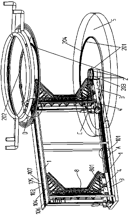
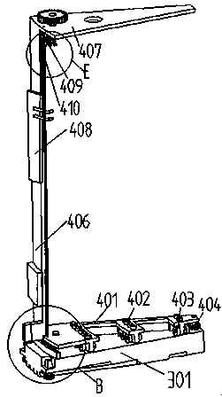
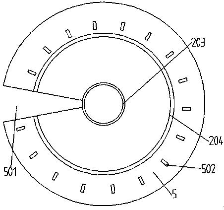
[0041] like figure 1 , figure 2 , image 3 , Figure 4 , Figure 5 , Image 6 , Figure 7 , Figure 8 , Figure 9 and Figure 10 The refueling system of the fusion and fission cladding shown, the fusion and fission cladding includes 18 cladding modules, each cladding module is the same and is an independent structure, and the cladding modules are spliced ​​and wrapped in the fusion target chamber to form a 360° cladding system, the fusion fission cladding refueling system includes a radial track 1, a circular track 2, a radial trolley 3 and a circular trolley 4, the radial trolley 3 is installed on the radial track 1, and the radial trolley The track 1 is arranged in the radial direction of the circular track 2 and extends to the circular track 2, the radial trolley 3 is equipped with a circular trolley 4, and the circular trolley 4 can switch from the radial trolley 3 to the circular track 2 for circular movement; it also includes an integrated cladding installation part 6 for installing the last cladding module 8 and a welding trolley 7 that can move on the radial rail 1, and the cladding installation part 6 includes a The support trolley 9 moving on the radial track 1 and the cladding module fixedly installed on the support trolley 9, so that when the last cladding module is installed, the cladding installation part 6 can be directly pushed into the installation area.
[0042] The radial track 1 includes a radially lower track 101 and a radially upper track 107 installed along the radial direction of the circumferential track 2. Since the cladding module is longitudinally installed on the circumferential dolly 4, two tracks are required, thereby To ensure the safety of the cladding module installed and to increase the moving speed of the trolley, the radial upper track 107 is installed above the radial lower track 101 through a bracket; the radial lower track 101 includes at least two tracks, thereby ensuring that the radial trolley Reliable movement on the radial track, the two sides of the radial lower track 101 are provided with gear rails 102 with tooth surfaces outward, and the radial upper track 107 includes a left track 103 and a right track 104 installed in parallel, and the left track 103 and the right track 104 are located on the same On the plane, the left track 103 or the right track 104 is provided with a guide tooth 105, the guide tooth 105 is located between the left track 103 and the right track 104, and the first guide tooth 105 is installed between the left track 103 and the right track 104. A gear 106, the guide tooth 105 is fitted with a driving motor, so that the drive force can be provided for the radial trolley to move on the radial track 1, and the guide tooth 105 is located between the left track 103 and the right track 104, which can avoid radial The car tilts left and right.
[0043] Described radial trolley 3 comprises sectoral car body 301, and the bottom of described car body 301 is equipped with roller, and described car body both sides is installed with the 4th gear 302 that cooperating with cog rail 102 is installed, and described 4th gear cooperates A drive motor is installed, so that the fourth gear 302 can be driven by the motor, so that the fourth gear can be rotated, and cooperate with the rack 102 to provide a driving force for the radial trolley to move on the radial rail, so that the radial trolley moves along the The radial track moves to transport the hoop trolley to the set position, and the top surface of the trolley body 301 is provided with a rack 303 .
[0044] The hoop trolley 4 includes an "E"-shaped frame body 401, a hydraulic cylinder 402 and a rolling wheel set 403. The frame body 401 is fan-shaped, and at least two rows are installed on the bottom of the frame body 401 to move in the same direction. rolling wheel sets 403, and each row of rolling wheel sets 403 is installed with the center of the outer gear rail 204 as the center of the circle, forming an outwardly diffused circular arc rolling wheel set, the center of circle of each row of rolling wheel sets is the same, and the frame body At least two rows of hydraulic cylinders 402 are installed on the top surface of 401, and the arrangement of hydraulic cylinders 402 can be the same as that of the rolling wheel sets, above each row of rolling wheel sets; the bottom of the cladding module 8 is provided with at least two rows of support seats 801 , the height of the support base 801 is higher than the height of the hoop trolley, and the support base 801 can be snapped into the "E"-shaped gap of the frame body 401, so that the cladding module can be easily installed on the hoop trolley, and at the same time, It is convenient to unload the cladding module from the hoop trolley, and the hoop trolley moves to the bottom of the cladding module, and the cladding module is lifted off the ground by lifting the hydraulic cylinder 402, so that the cladding module can be quickly installed On the hoop trolley, when it is necessary to unload the cladding module from the hoop trolley, the hydraulic cylinder is controlled to shrink, so that the support seat of the cladding module is pressed against the ground or the top surface of the base, so that the hoop trolley can Withdraw from the bottom of the cladding module.
[0045] The outer arc end of the frame body 401 is provided with a vertically installed support portion 406, and the top of the support portion 406 is equipped with a slide plate 407 that cooperates with the right guide rail or the left guide rail, and the slide plate 407 is located on the left track 103 and Between the right rails 104, the top of the slide plate 407 is provided with a first gear 106 that can cooperate with the guide teeth 105 on the left rail 103, the first gear 106 rotates, and the driving ring moves along the radial rail 1 to the dolly 4; The outer arc end and the inner arc end of the body 401 are respectively equipped with a second gear 404 and a third gear 405, and the top surface of the radial trolley 3 is equipped with a sub-rack 303 that cooperates with the third gear 405. The gear 106, the second gear 404 and the third gear 405 are all provided with a drive motor; the support portion 406 is provided with a mechanical arm for welding and cutting pipes, and the welding trolley 7 includes a bottom surface provided with radial rails. Cooperate with the base 701 of the installed roller and the support 702 that is located on the base and is equipped with a mechanical arm; the support part 406 is provided with a vertically installed threaded rod 410, and the mechanical device for welding and cutting pipelines is installed on the threaded rod. Arm 409.
[0046] The circular track 2 includes a lower ring rack 201, the lower ring rack 201 includes a circular inner rack 203 and an outer rack 204 installed outside the inner rack 203, the inner rack teeth 203 and the outer gears The rails 204 have the same center, the tooth surface of the outer rack 204 is inward, and the tooth surface of the inner rail tooth 203 is outward. The outer rack 204 is provided with an opening at the installation radial track 1, and the length of the divided rack 303 is exactly the same as The openings on the outer rack 204 are the same, and the distance from the divided rack 303 to the inner rack 203 is the same as the distance from the outer rack 204 to the inner rack 203;
[0047] The center line of the upper ring rack 202 coincides with the center line of the lower ring rack 201 and is installed above the lower ring rack 201, and the tooth surface of the upper ring rack 202 is outward;
[0048] The installation distance between the second gear 404 and the third gear 405 is that when the second gear 404 on the hoop trolley meshes with the inner rack 203, the third gear 405 meshes with the outer rack 204, and at this time, the second A gear 106 meshes with the upper ring rack 202, and the first gear 106, the second gear 404, and the third gear 405 rotate synchronously so that the cladding module can be transported to a designated position; the radius of the sub-rack and the radius of the outer rack 204 same radius.
[0049] The lower ring rack 201 is installed on the base 5, and the base 5 is provided with a fan-shaped base opening 501, and the hoop trolley 4 and the radial trolley 3 can both drive into the base opening 501, and the hoop trolley The trolley 4 can just fill the opening 501 of the base, the top surface of the trolley 4 and the top surface of the base 5 are on the same plane, the opening of the base 501 is in the same direction as the opening on the outer gear rail 204, and the opening size is the same , the radially lower rail 101 extends into the base opening 501; a water tank 408 is installed on the support portion 406 of the circular trolley 3, a reserved pipeline is installed on the water tank, and a fuel module of the cladding module is installed with Reserved pipes, when disassembling the cladding module, after closing the valve of the cladding module and the main pipeline, the remaining pipes on the water tank are connected to the reserved pipes on the cladding module, and a water pump is installed in the water tank, and the water pump drives the water in the water tank. Water enters the internal circulating cooling pipeline of the module, and the cladding module is cooled. The base 5 is provided with a positioning block 502, and the circumferential trolley is provided with a positioning bump 503 that cooperates with the positioning block. The positioning block 502 is installed on the outer tooth On the periphery of the rail 204, each cladding module is correspondingly equipped with a positioning block, the radius of the first positioning block 502 increases gradually to the radius of the last positioning block 502, and when the corresponding cladding module is installed, the positioning protrusion The length is just blocked by the corresponding positioning block 502, so that the cladding module can be installed precisely.
[0050] In the assembly and disassembly method of the fusion and fission cladding refueling system of the present invention, the fusion and fission cladding includes several identical cladding modules, including the steps of installing the cladding module and disassembling the cladding module, and installing the cladding module:
[0051] a. Install the hoop trolley 4 on the radial trolley 3, install the cladding module 3 on the hoop trolley, and the hydraulic cylinder on the hoop trolley lifts the cladding module to prevent the cladding module from contacting the ground. A positioning bump of corresponding length is installed on the hoop trolley;
[0052] b. Make the radial trolley 3 move to the set position along the radial track 1 to the circular track 2, make the circular trolley 4 cooperate with the circular track 2, and make the circular trolley 4 move along the circular track 2 to install each cladding module In step b, make the radial trolley 3 move to the set position along the radial track 1 to the circular track 2 to move the radial trolley to the base opening 501, that is, move the radial trolley to the rack 303 Connect with the outer rack 203, so that the first rack meshes with the upper ring rack, the second gear 404 meshes with the inner rack 204, and the sub-rack 303 meshes with the third gear 405;
[0053] c. Control the first gear, the second gear and the third gear to rotate synchronously, so as to drive the hoop to move to the trolley. After the hoop trolley 4 moves to the position where the cladding module is installed, the positioning block fits with the positioning bump and passes the sensor Send a feedback signal to the gear drive motor to stop the drive motor, thereby positioning the cladding module. Each cladding module adopts this positioning method, relying on the positioning block on the shielded layer to ensure positioning accuracy, and there will be no Accumulate errors to increase the accuracy of positioning, and then control the hydraulic cylinder to descend, so that the support seat of the cladding module is supported on the base 5. At this time, the pipe on the module and the branch pipe under the system main pipe (that is, the outside of the cladding module Pipelines) are basically aligned, and the mechanical arm is controlled to realize the alignment and positioning of the pipes. The welding robot welds the pipes, and then controls the rotation of the first gear, the second gear and the third gear, so that the hoop trolley withdraws from the bottom of the cladding module ;
[0054] d. Control the circular trolley 4 to move back to the radial trolley 3 along the circular track 2, control the radial trolley 3 to return to the starting point on the radial track 1, and install the next cladding module on the circular trolley 4 , to install the next cladding module;
[0055] e. Repeat steps a, b, c and d until the penultimate cladding module 3 is installed, then remove the radial trolley 3, and install the cladding installation part 6 on the radial rail 1, so that the cladding is installed Part 6 moves to the installation position of the last cladding module 3, that is, the base opening position of the base 5, and then installs the welding trolley 7 on the radial rail 1, so that the welding trolley moves to the outside of the cladding installation part 6, and controls The mechanical arm welds the pipeline in the cladding installation part 6 with the external circulation pipeline, then withdraws the welding trolley, and then drives out the strut installed between the inner and outer shielding layers through a hydraulic rod to withstand the cladding module, thereby Provide horizontal and vertical pressure to the cladding module to complete the installation of the entire cladding system;
[0056]Disassemble the cladding module:
[0057] Removing the cladding module is opposite to the process of installing the cladding module. f. Remove the last cladding module installed first, that is, first move the welding trolley to the outside of the cladding installation part 6 and use the mechanical arm to remove the cladding module on the cladding installation part 6. The pipeline is cut from the external circulation pipeline, and then the cladding installation part 6 is moved to the outermost end of the radial guide rail, the cladding installation part 6 is removed, and the radial trolley 3 equipped with the hoop trolley 4 is installed on the On the radial track 1; when the cladding module is disassembled, the fission products in the cladding module will continue to decay and generate heat, which means that the temperature of the module will continue to rise during the disassembly process, causing some safety hazards and increasing the difficulty of disassembly. When the cladding module is installed, after closing the valve of the cladding module and the main pipeline, the reserved pipeline of the cladding module is connected with the reserved pipeline on the water tank on the hoop trolley, and the water pump drives the water in the water tank to enter the cladding module to circulate the cladding module After cooling, the ring trolley disassembles and transports the module out, pumps out the hot water from the water tank and injects cold water to prepare for the next module to be disassembled. The cooling water tank is in the shape of a cuboid and is installed on the back of the hoop trolley. Two reserved pipes protrude from the water tank.
[0058] g. Move the radial trolley 3 to the position of the base opening 501, move the circular trolley 4 to the bottom of each cladding module, control the hydraulic cylinder to lift the cladding module, and then move the circular trolley 4 to the radial trolley (3) On, move the radial trolley 3 to the outer end of the radial track 1, and remove the cladding module 8;
[0059] h. Repeat step g to remove all cladding modules.
[0060] In summary, the fusion-fission cladding refueling system and its refueling method of the present invention overcome the complexity of small module manifolds, large flow resistance, low heat exchange efficiency, large assembly workload, low welding reliability and low refueling efficiency, Disadvantages of complex refueling process; reduced fluid resistance in the tube, increased flow rate of a single cladding module, improved Z-pinch driven fusion-fission hybrid reactor subcritical energy cladding heat exchange capacity; reduced cladding module The difficulty of installation is beneficial to the later inspection, maintenance and refueling.
[0061] The above is only an embodiment of the present invention, and does not limit the patent scope of the present invention. Any equivalent structure or equivalent process transformation made by using the description of the present invention and the contents of the accompanying drawings, or directly or indirectly used in other related technologies fields, are all included in the scope of patent protection of the present invention in the same way.

PUM

no PUM

Description & Claims & Application Information

We can also present the details of the Description, Claims and Application information to help users get a comprehensive understanding of the technical details of the patent, such as background art, summary of invention, brief description of drawings, description of embodiments, and other original content. On the other hand, users can also determine the specific scope of protection of the technology through the list of claims; as well as understand the changes in the life cycle of the technology with the presentation of the patent timeline. Login to view more.
Why Eureka
Try Eureka