Wire rod processing equipment

A technology for processing equipment and wires, applied in the field of wire processing equipment, can solve problems such as low efficiency, high temperature of welding consumables, burns, etc., and achieve the effect of high work efficiency

Pending Publication Date: 2019-05-28
SHENZHEN EX LIGHTING TECH HLDG
View PDF0 Cites 6 Cited by
  • Summary
  • Abstract
  • Description
  • Claims
  • Application Information

AI Technical Summary

Problems solved by technology

[0002] When traditional processing equipment processes wires, it is necessary to peel off the wires that have been cut and removed from the sheath, and then apply welding consumables such as tin liquid and flux to the surface of the exposed wire core after stripping the sheath. Therefore, Generally, a cutting mechanism is used to cut off the wire sheath of the wire, and the stripping clip clamps the wire and pulls the wire in a predetermined direction to peel the wire sheath from the wire. After stripping the wire sheath, the exposed wire core is manually dipped and coated with flux. The welding consumables such as solder and tin liquid are not only inefficient, but also the temperature of the welding consumables in the molten state is high, and there is a safety hazard of being scalded by manual operation

Method used


Image

  • Wire rod processing equipment
  • Wire rod processing equipment
  • Wire rod processing equipment

Examples


Embodiment Construction

[0028] The present application will be described in further detail below in conjunction with the accompanying drawings and specific embodiments. It should be understood that the following exemplary embodiments and descriptions are only used to explain the present invention, not as a limitation to the present invention, and, in the case of no conflict, the embodiments in the application and the features in the embodiments can be combined with each other .

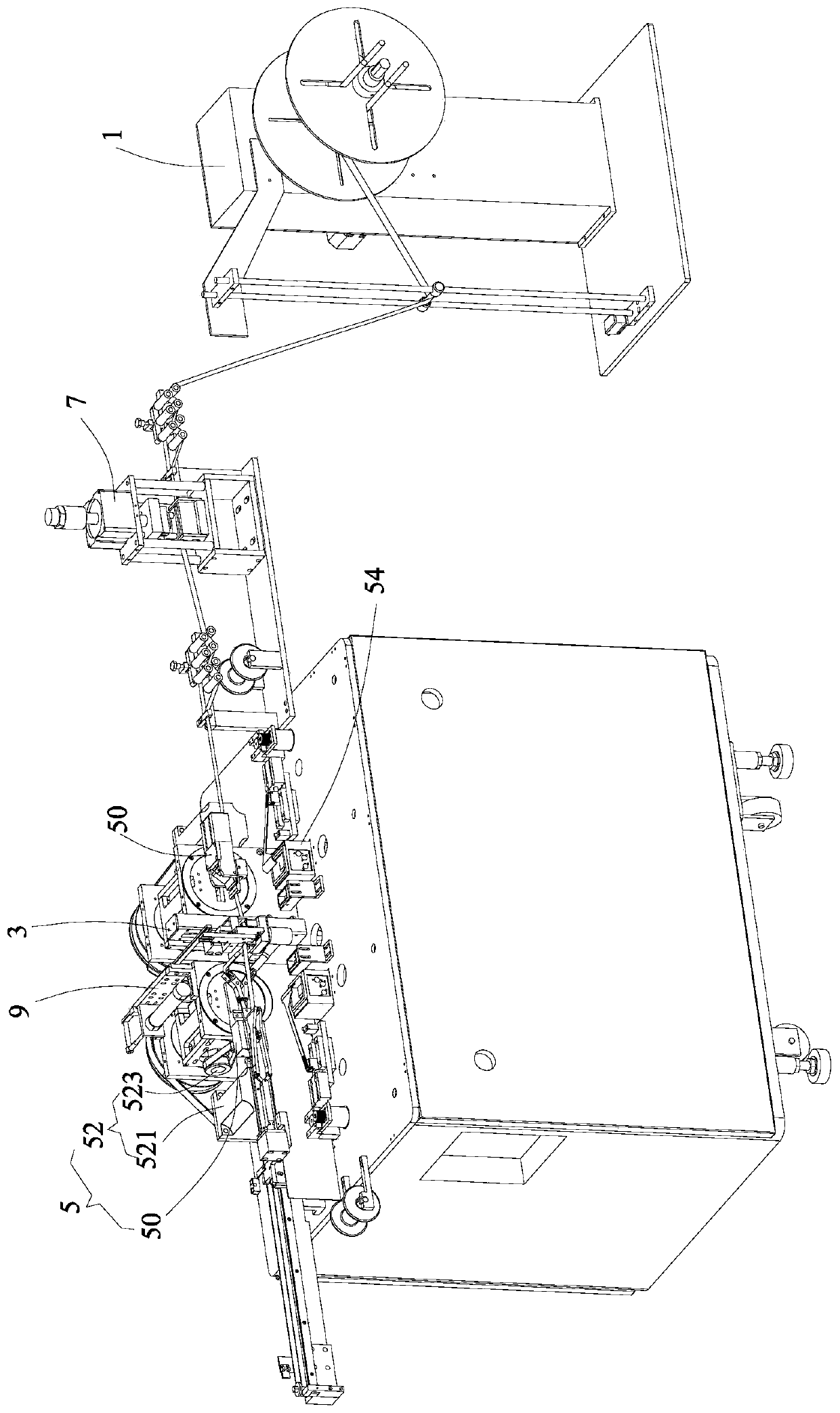
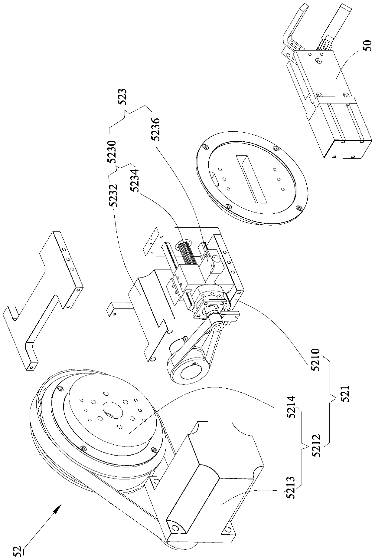
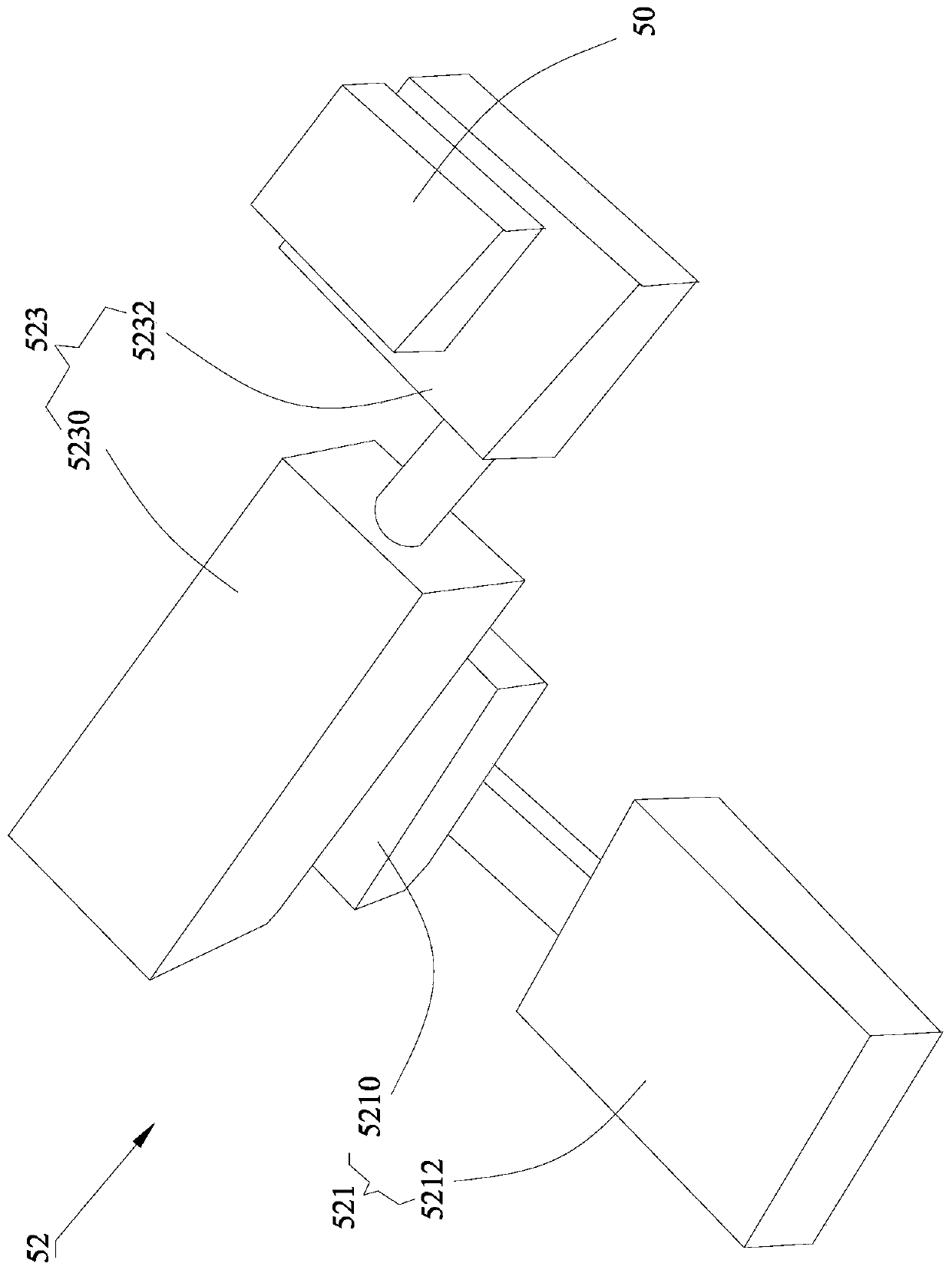
[0029] Such as Figure 1 to Figure 2 As shown, the embodiment of the present invention provides a wire processing equipment, including a feeding device 1 for continuously supplying wire strips, for sequentially cutting the wire strips according to predetermined lengths to obtain wire segments and separating the wire sheaths of the wire strips at a distance from the wire The cutting device 3 that is cut off at a position with a predetermined distance from the cutting place and the stripping device 5 that is located on the do...


PUM


Abstract

The embodiment of the invention provides wire processing equipment. The equipment comprises a feeding device for feeding a wire belt, a cutting device which is used for cutting a wire rod strip according to a preset length to obtain a wire rod section and cutting the skin of the wire rod strip at a preset position, and a wire stripping device which is arranged at the downstream side of the cuttingdevice. The wire stripping device comprises a wire stripping clamp and a power mechanism used for driving the wire stripping clamp to horizontally reciprocate in a wire rod strip conveying directionand rotate around the horizontal axis perpendicular to the wire rod strip conveying direction. An accommodation groove used for accommodating welding consumables is formed below the wire stripping clamp. The power mechanism comprises a first power module and a second power module fixed to the output end of the first power module. The wire stripping clamp is fixed to the output end of the second power module, wherein one of the first power module and the second power module is a power module for outputting linear motion power, and the other one is a power module for outputting rotary motion power. According to the embodiment of the invention, the efficiency of adhering welding consumables to wires and stripping wire skins can be improved.

Description

technical field [0001] Embodiments of the present invention relate to the technical field of wire processing, and in particular, to a wire processing device. Background technique [0002] When traditional processing equipment processes wires, it is necessary to peel off the cut and cut wires first, and then apply welding consumables such as tin liquid and flux to the surface of the exposed wire core after stripping the wires. Therefore, Generally, a cutting mechanism is used to cut off the wire sheath of the wire, and the stripping clip clamps the wire and pulls the wire in a predetermined direction to peel the wire sheath from the wire. After peeling off the wire sheath, the exposed wire core is manually dipped and coated with flux. Soldering consumables such as solder and tin liquid are not only inefficient, but also have a high temperature in the molten state, and there is a safety hazard of being scalded by manual operation. Contents of the invention [0003] The tech...

Claims


Application Information

Patent Timeline
Patent Type & Authority Applications(China)
IPC IPC(8): H01R43/28
Inventor 郭群涛张玉刚
Owner SHENZHEN EX LIGHTING TECH HLDG
Why Eureka
Try Eureka