Multi-cavity pipe for hole opening in partition wall for flexible transmission
A technology of flexible transmission and partition wall, which is applied in catheters, medical science, surgery, etc., can solve the problems of particles entering the human body and cannot be solved, and achieve the effect of improving passing capacity, reducing parts, and reducing length
- Summary
- Abstract
- Description
- Claims
- Application Information
AI Technical Summary
Problems solved by technology
Method used
Image
Examples
Embodiment 1
[0033] Embodiment 1 (Using the opening position of the partition wall and the flow limiting part of the transmission chamber to control the return flow)
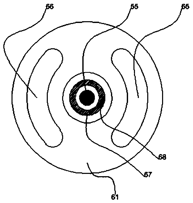
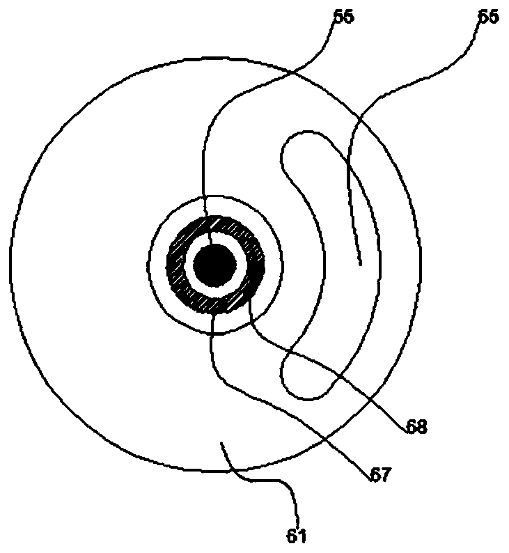
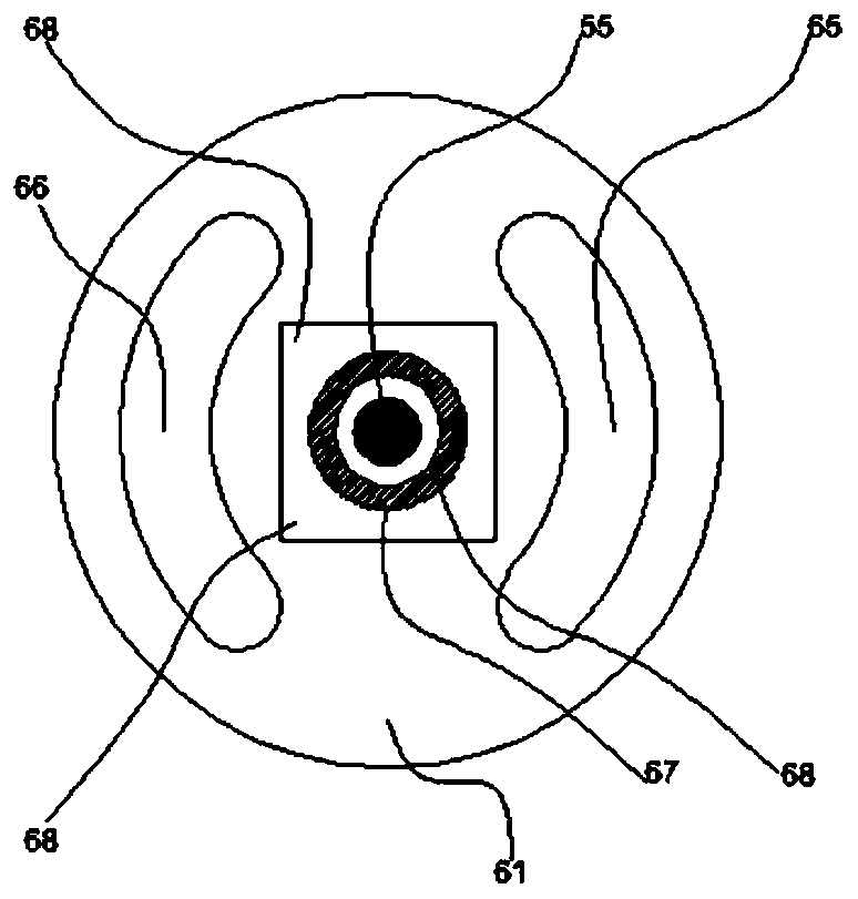
[0034] In this embodiment, a multi-lumen tube with a length of 1200 mm is taken as an example. The multi-lumen tube disclosed in this embodiment includes a tube body 61, inside the tube body 61 there are a plurality of channel cavities distributed along the axis of the tube body 61, and the channel cavities are separated from each other by partition walls. In this embodiment, the channel cavity includes a central transmission cavity 68 and a perfusion cavity one 65 . The transmission chamber 68 communicates with the perfusion chamber 1 65 through at least one opening on the partition wall. In this embodiment, the opening is located 20 mm from the distal end toward the proximal end in the axial direction of the tube body 61 , and the hydraulic diameter of the opening is 0.8 mm. There is a flexible drive shaft 55 inside the ...
Embodiment 2
[0038] Embodiment 2 (Using the opening position of the partition wall and the flow limiting part of the transmission chamber, the remote flow limiting part cooperates with the rigid shaft to jointly control the return flow)
[0039] The difference between this embodiment and Embodiment 1 is that: the position of the opening on the partition wall between the transmission chamber 68 and the perfusion chamber 1 65 is located 10 mm from the distal end to the proximal end of the tubular body 61 in the axial direction. The distal end of the flexible driving shaft 55 is connected with the rotating function part 41 through the distal rigid shaft 51 , and the distal end of the flexible driving shaft 55 is connected with the distal rigid shaft 51 through an adapter 54 . The distal end of the tube body 61 is sealingly connected with the fixed packaging shell 70 . The fixed packaging shell 70 is used to accommodate the distal restrictor 52 and the distal rigid shaft 51 , providing a seale...
Embodiment 3
[0042] Embodiment 3 (Using the opening position of the partition wall and the flow-limiting part of the transmission chamber, the distal flow-limiting part and the rigid shaft cooperate to control the return flow, and at the same time, add a perfusion pipeline to directly control the perfusion into the human body)
[0043] The difference between this embodiment and embodiment 2 lies in that: a perfusion cavity, ie perfusion cavity two 66 , is added in the tube body 61 . The perfusion solution is poured into the first perfusion chamber 65 and the second perfusion chamber 66 by different infusion bags 60 and perfusion pumps or pressure bags 57 . The flow ratio of the cooling liquid poured into the human body and returned to the body can be adjusted according to actual needs, and the free adjustment of the flow ratio of 1 to 300 times can generally be realized. The hydraulic diameter of the perfusion chamber 2 66 is 0.5mm. The outlet of the distal end of the perfusion chamber 2 ...
PUM
 Abstract
Description
Claims
Application Information
 - R&D
- Intellectual Property
- Life Sciences
- Materials
- Tech Scout
- Unparalleled Data Quality
- Higher Quality Content
- 60% Fewer Hallucinations
Browse by: Latest US Patents, China's latest patents, Technical Efficacy Thesaurus, Application Domain, Technology Topic, Popular Technical Reports.
© 2025 PatSnap. All rights reserved.Legal|Privacy policy|Modern Slavery Act Transparency Statement|Sitemap|About US| Contact US: help@patsnap.com


