Coal-fired power plant fly ash rapid quantitative loading station and method

A technology of coal-fired power plants and fly ash, which is applied in the field of automatic mechanical devices and bulk cargo loading to achieve the effects of promoting flow, improving wear resistance, and avoiding agglomeration

Inactive Publication Date: 2019-05-31
TIANDI SCI & TECH CO LTD +1
View PDF4 Cites 2 Cited by
  • Summary
  • Abstract
  • Description
  • Claims
  • Application Information

AI Technical Summary

Problems solved by technology

[0004] The existing rapid quantitative loading system is mostly used in coal, and the environment of the ash storage yard of the power plant and the characteristics of the fly ash of the power plant are quite different from those of coal.

Method used


Image

  • Coal-fired power plant fly ash rapid quantitative loading station and method
  • Coal-fired power plant fly ash rapid quantitative loading station and method

Examples


Embodiment 1

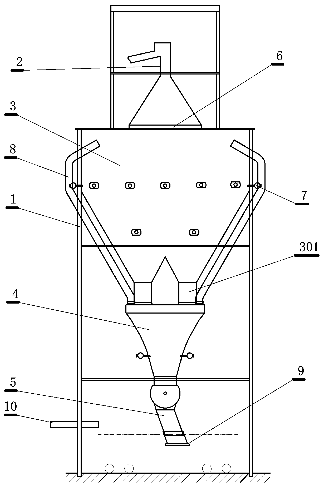
[0024] This embodiment is a fast quantitative loading station for fly ash of a coal-fired power plant, such as figure 1 shown. The present embodiment comprises: frame 1, described frame is provided with conveyer belt head 2, buffer bin 3, quantitative bin 4, swing chute 5 sequentially from top to bottom, described conveyor belt head, buffer bin, quantitative bin and A sealing facility 6 is provided between the swinging chutes, and the buffer bin is provided with at least four outlets 301, and the weighing bin body of the weighing bin is inwardly curved, and is lined with a polyurethane liner. At least one layer of air cannons 7 are evenly distributed around the surrounding walls of the buffer storehouse and the quantitative storehouse, and the nozzles of each air cannon are arranged downward along the storehouse wall. The quantitative storehouse is provided with at least two ventilation pipes 8, so One end of the ventilation pipe is arranged on the top of the quantitative war...

Embodiment 2

[0042] This embodiment is an improvement of the first embodiment, and is a refinement of the first embodiment on the sealing facilities. The sealing facility described in this embodiment is that a flexible connection sealing cover is provided between the conveyor belt machine head and the buffer bin, between the buffer bin and the quantitative bin, between the quantitative bin and the swing chute, and the buffer bin and the quantitative bin Use a gasket seal on the setting gate.

[0043] The sealing facility is a system, distributed in multiple parts of the loading station, mainly composed of various baffles, maintenance structures, seals, etc.

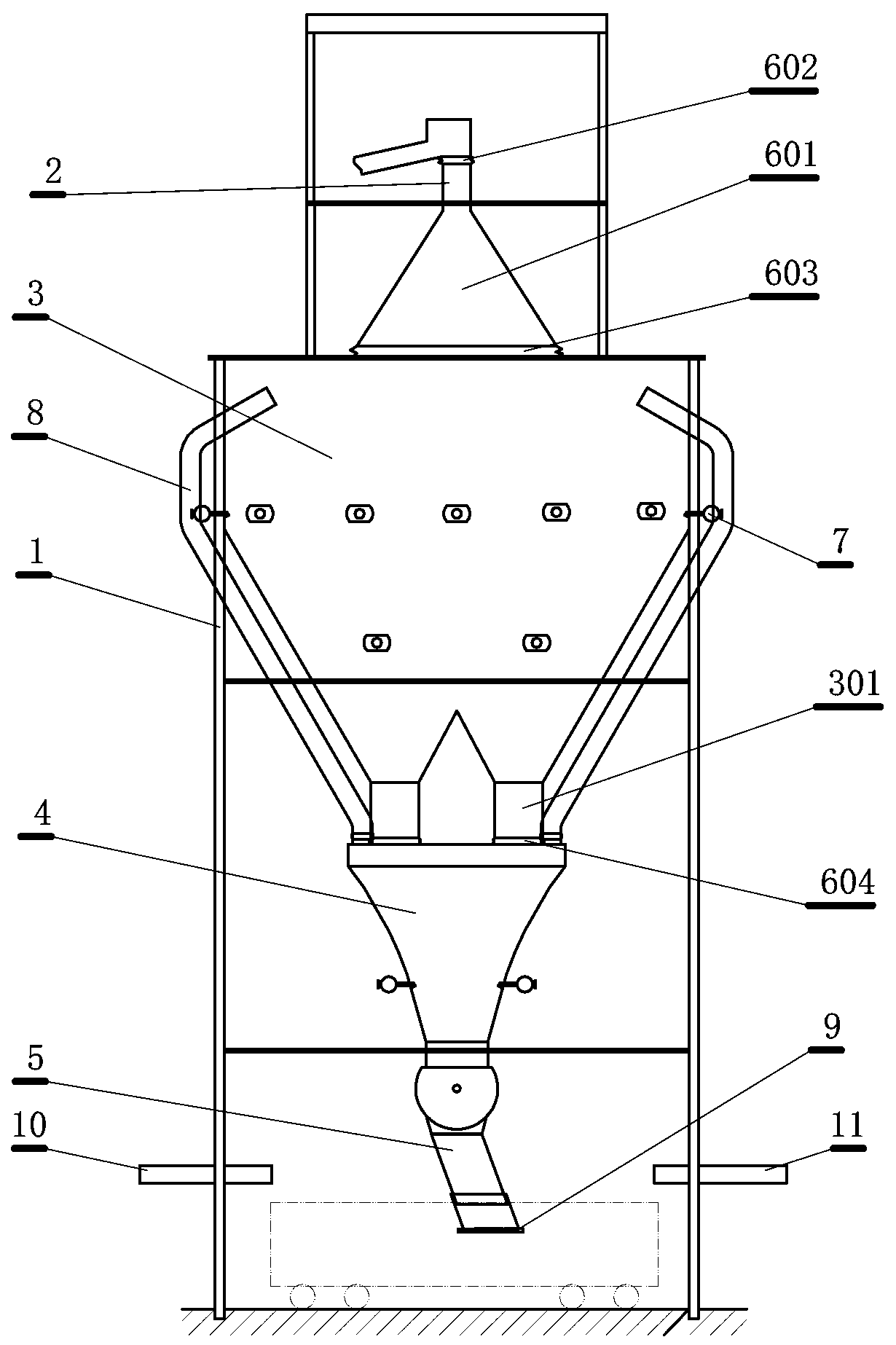
[0044] Between the head of the conveyor belt and the buffer warehouse, the head guard plate 601 (such as figure 2 As shown) seal the conveyor belt head and the feed inlet of the buffer bin in a narrow space that only allows the material to go from the conveyor belt to the buffer bin inlet, so as to avoid the scattering and diffusion...

Embodiment 3

[0049] This embodiment is an improvement of the first embodiment, and is a refinement of the first embodiment on the buffer gate. Each discharge port of the buffer bin described in this embodiment is respectively provided with a double-wing gate with a stainless steel and rubber seal dust-proof design. Lubricate wear-resistant slides.

[0050] The split double-wing gate is easy to seal and has a fast opening and closing speed, especially suitable for bulk materials with fine particles. The gate is dust-proof with stainless steel and rubber seal. The upper surface of the gate is covered with a thick 10mm wear-resistant plate to prolong the service life. The lower part is equipped with a high-strength non-lubricating wear-resistant slider, which does not need to install an automatic lubrication device.


PUM


Abstract

The invention relates to a coal-fired power plant fly ash rapid quantitative loading station and method. Sealing facilities are arranged between a conveyor belt machine head, a buffer bin, a quantitative bin and a swing chute, the buffer bin is provided with at least four discharge ports, the weighing bin body of a weighing bin is a hyperbolic liner polyurethane lining plate which is bent inwards,at least one layer of air cannons are uniformly distributed on the periphery bin wall of the buffer bin and the periphery bin wall of the quantitative bin respectively, nozzles of all the air cannonsare arranged downwards along the bin walls, one end of a vent pipe is arranged at the top of the quantitative bin, and the other end of the vent pipe is arranged in the position, close to the top, ofthe buffer bin. The buffer bin provided by the invention is provided with a plurality of material outlets, the quantitative bin adopts a hyperbolic bin wall, the bin wall is quite steep, so that rapid agglomeration of fly ash is avoided, the fly ash flows downwards easily, and meanwhile, the air cannons are arranged to promote the flow of the fly ash and effectively avoid agglomeration. Meanwhile, sealing is carried out between each cabin in the whole loading process to prevent leakage of the fly ash.

Description

technical field [0001] The invention relates to a rapid and quantitative loading station and method for fly ash of a coal-fired power plant, which is an automatic transportation device and method, and an automatic mechanical device and method for loading bulk goods. Background technique [0002] Electricity is an important energy source for the development of the national economy, and thermal power generation is the main method for producing electric energy in China and many countries in the world. The by-product solid waste (mainly fly ash) produced by coal-fired thermal power plants is more than 100 million tons per year. The comprehensive utilization of power plant fly ash directly affects the economic, social and environmental benefits of coal-fired power plants. [0003] In order to realize the comprehensive utilization of power plant fly ash, the primary problem to be solved is the transportation of power plant fly ash. Scattered loading in the open will cause a lot ...

Claims


Application Information

Patent Timeline
Patent Type & Authority Applications(China)
IPC IPC(8): B65G67/06B65D88/70B65G69/18B65D90/04
Inventor 李旭刘竞雄孙国顺袁华常杰云栗伟张兆杰田钰张海聪
Owner TIANDI SCI & TECH CO LTD
Why Eureka
Try Eureka