Hydraulic engine powered winch

A winch mill, hydraulic technology, applied in the direction of the spring mechanism, hoisting device, etc., can solve the problems of hidden safety hazards, high technical requirements of operators, and limited braking area.

Inactive Publication Date: 2019-05-31
泰州市昊鑫电力机具有限公司
View PDF5 Cites 1 Cited by
  • Summary
  • Abstract
  • Description
  • Claims
  • Application Information

AI Technical Summary

Problems solved by technology

[0002] The existing motorized winch mill does not meet the requirements of UHV transmission lines due to potential safety hazards in braking and complicated operation
Belt transmission is used between the prime mover and the reducer, which has low transmission efficiency and is easy to slip. In the previous design, the brake was designed in the reducer box. Limited by the size of the reducer box, the braking area is limited, resulting in small braking force and poor heat dissipation effect. , can not meet the braking requirements when working at full load for a long time, and there are potential safety hazards
Manual clutch, easy to start and stop the engine
Moreover, the existing winch cannot display the traction force, and the gears are only 3 gears, which cannot meet the needs of users for different speeds, so the technical requirements for operators are high

Method used


Image

  • Hydraulic engine powered winch
  • Hydraulic engine powered winch
  • Hydraulic engine powered winch

Examples


Embodiment 1

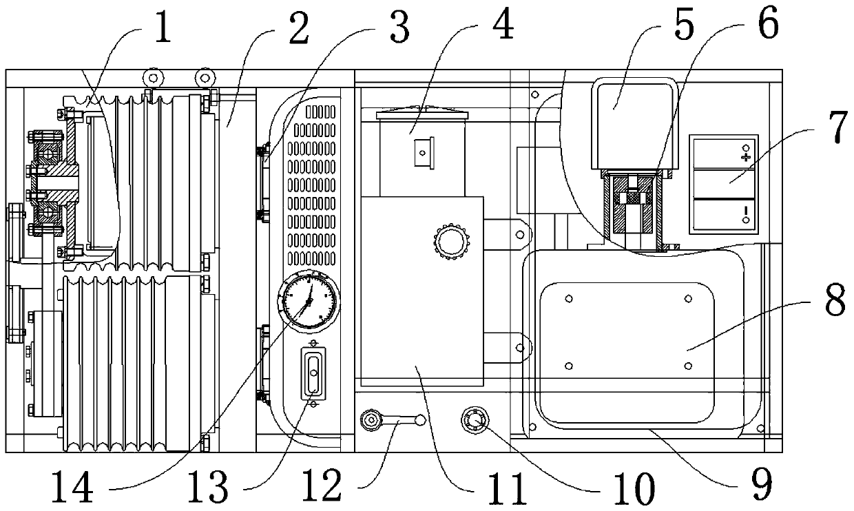
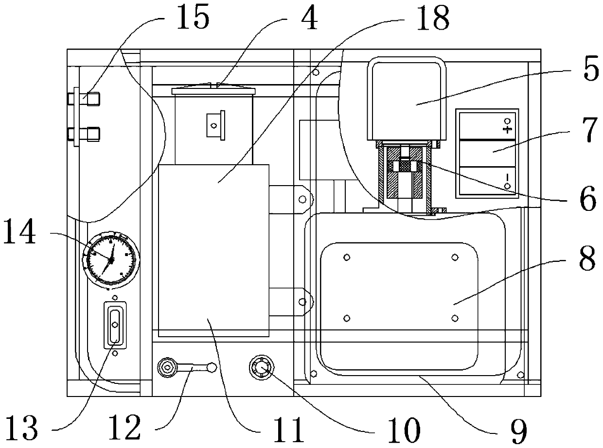
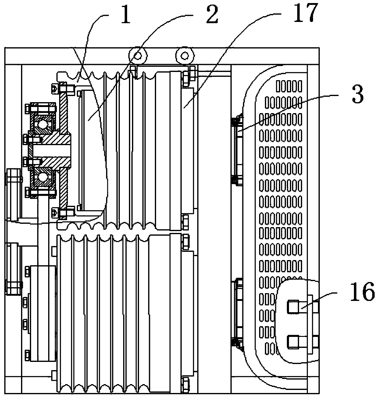
[0040] like Figure 1-Figure 3 As shown, the hydraulic winch mill includes a gasoline engine 8, a hydraulic variable pump 5, and a drum 1. A gasoline tank 9 is arranged behind the gasoline engine 8 to store gasoline. A coupling 6 is arranged on the gasoline engine 8 to transmit power. The coupling 6- A battery 7 is arranged on the side to provide starting power, a hydraulic variable pump 5 is arranged on the coupling 6 to generate hydraulic pressure, a radiator 11 is arranged on one side of the gasoline engine 8 to increase heat dissipation of the hydraulic oil tank 18, and a hydraulic oil tank is arranged behind the radiator 11 18, containing hydraulic oil, a filter 4 is arranged on the hydraulic oil tank 18 to filter the hydraulic oil, and a relief valve 10 is arranged in front of the radiator 11, and the maximum traction force is limited by adjusting the size, and a ball valve is arranged on the side of the relief valve 10 12. It is used to control the work of the brake 17....

Embodiment 2

[0042] The difference between this embodiment and embodiment 1 is:

[0043] The coupling 6 is respectively connected with the gasoline engine 8 and the hydraulic variable displacement pump 5 using a flat key, and the flat key connection facilitates the smooth transmission of the power of the gasoline engine 8 to the hydraulic variable displacement pump 5 .

[0044] Working principle: The gasoline engine 8 burns gasoline to generate power, and the power is transmitted to the hydraulic variable pump 5 through the coupling 6, and the hydraulic variable pump 5 converts mechanical energy into hydraulic energy, and then passes through the middle of the first quick-change joint 15 and the second quick-change joint 16 The connected oil pipe transmits the hydraulic energy to the hydraulic motor 3. The hydraulic motor 3 converts the hydraulic energy into mechanical energy and transmits it to the reducer 2. The reducer 2 transmits the mechanical energy to the drum 1 after decelerating and...


PUM


Abstract

The invention discloses a hydraulic engine powered winch. The hydraulic engine powered winch comprises a gasoline engine, a hydraulic variable pump and a roller; a gasoline tank is arranged behind thegasoline engine, a coupler is arranged on the gasoline engine, an electric bottle is arranged on one side of the coupler, and the hydraulic variable pump is arranged on the coupler; and a radiator isarranged on one side of the gasoline engine, a hydraulic oil tank is arranged behind the radiator, a filter is arranged on the hydraulic oil tank, an overflow valve is arranged in front of the radiator, a ball valve is arranged on one side of the overflow valve, a hydraulic handle is arranged on one side of the ball valve, and an electric contact hydraulic pressure gauge is arranged above the hydraulic handle. The method has the beneficial effects that stepless variable speed can be realized, the requirements of a user for different speeds can be met, meanwhile, the load size can be displayed, so that a user can make a reasonable use method for judging the size of the load; and moreover, load size setting and load protection safety measures are provided, and therefore the convenience of using of the engine powered winch is improved.

Description

technical field [0001] The invention relates to the field of power laying equipment, in particular to a hydraulic winch mill. Background technique [0002] The existing motorized winch does not meet the requirements of UHV transmission lines due to potential safety hazards in braking and complicated operation. Belt transmission is used between the prime mover and the reducer, which has low transmission efficiency and is easy to slip. In the previous design, the brake was designed in the reducer box. Limited by the size of the reducer box, the braking area is limited, resulting in small braking force and poor heat dissipation effect. , cannot meet the braking requirements when working at full load for a long time, and there are potential safety hazards. Manual clutch, easy to start and stop the engine. Moreover, the existing winch cannot display the magnitude of the traction force, and the gears only have 3 gears, which cannot meet the needs of users for different speeds, s...

Claims


Application Information

Patent Timeline
IPC IPC(8): B66D1/08B66D1/58B66D1/54B66D5/00
Inventor 唐建涛高进美
Owner 泰州市昊鑫电力机具有限公司
Why Eureka
Try Eureka