
Eureka
For R&D, Eureka makes reading and utilizing patents & technical documents easy.
Eureka AIR
Designed for self-driven R&D workflows. Generate viable solutions, solve complex R&D challenges, empower your innovation with AI.

Eureka Materials
Designed for material experts only. Revolutionize your material R&D, from search, analyze, to developing new materials.

TechResearch
Generate reliable direction feasibility study reports for your R&D in just a few steps.

TechSeek
Discover and master advanced knowledge NOW. Basics, ideas, possibilities, all at once.

TechMind
As an expert in R&D Theories, TechMind can generates customized viable solutions instantly.

TechRisk
Analyze your overall solution with one click, know your potential R&D risks in advance.

TechMonitor
Get weekly tech updates, stay abreast of the latest tech innovations and key insights.
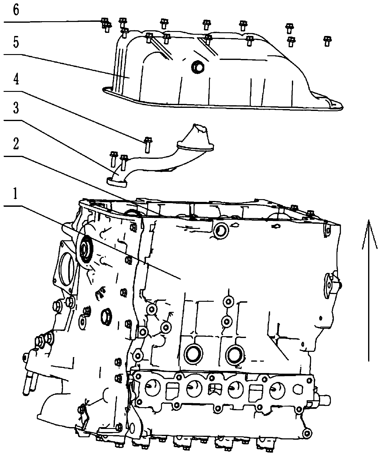
Engine oil collector and oil sump assembling device and assembling method thereof
An oil collector and engine oil technology, which is applied in the direction of engine components, machines/engines, and engine lubrication, can solve the problems of large space occupation, poor flexibility, and slow working efficiency of turning machines, so as to improve the utilization rate, good flexibility
- Summary
- Abstract
- Description
- Claims
- Application Information
AI Technical Summary
Problems solved by technology
Method used
Image

Examples
Embodiment Construction
[0038] In order to make the object, technical solution and advantages of the present invention clearer, the implementation manner of the present invention will be further described in detail below in conjunction with the accompanying drawings.
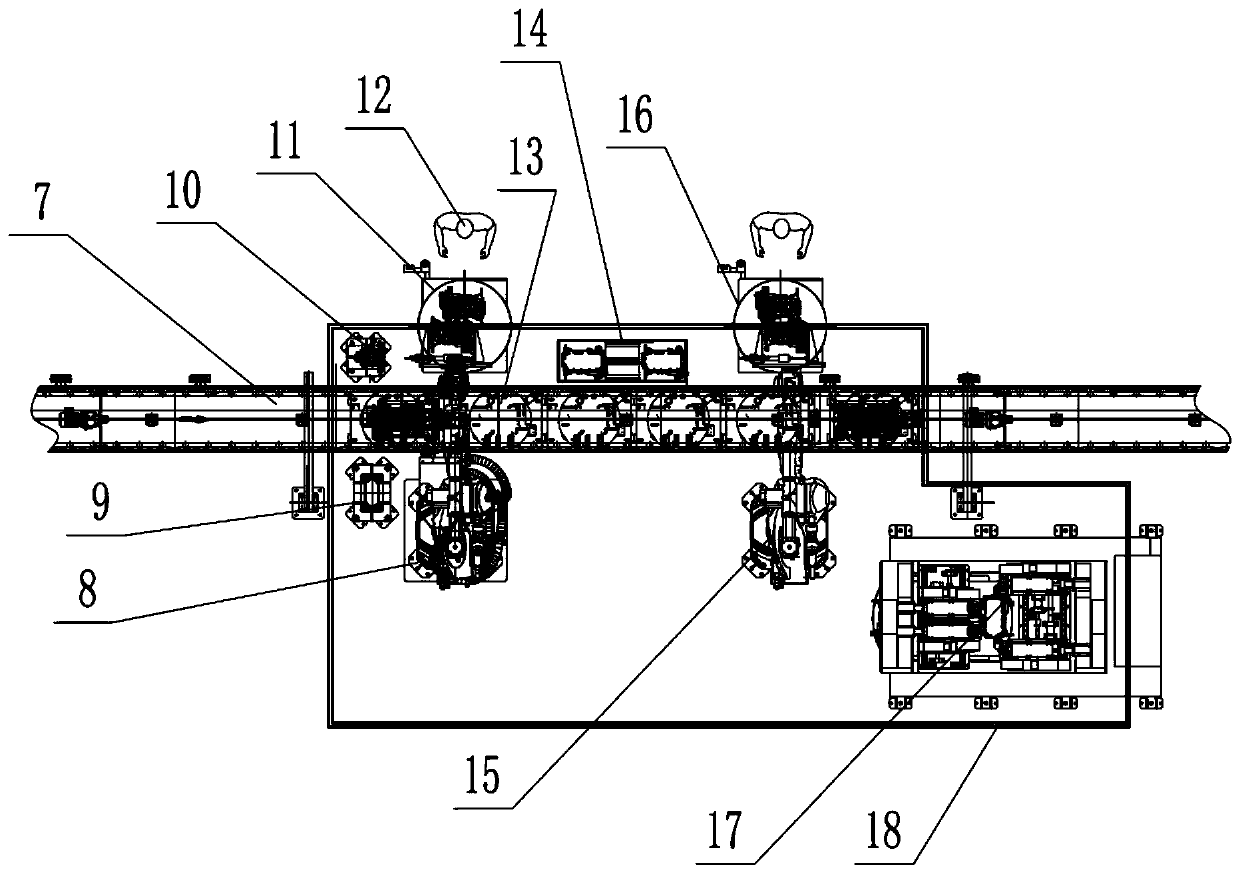
[0039] see figure 1 , an engine oil collector and oil pan assembly device, has:
[0040] Assembly line body, the assembly line body can transport the engine;
[0041] The oil collector sub-assembly turntable is set on one side of the assembly line body, and the operator can install the oil collector on the oil collector sub-assembly turntable;
[0042] The sliding shuttle table is set on one side of the assembly line body; the engine can apply glue on the sliding shuttle table;
[0043] The robot glue applicator is installed on one side of the assembly line body. The robot glue applicator can clamp the engine on the assembly line body and turn over the engine; the robot glue applicator can grip the engine to the oil collector, subpac...
PUM
 Abstract
Description
Claims
Application Information
 - R&D Engineer
- R&D Manager
- IP Professional
- Industry Leading Data Capabilities
- Powerful AI technology
- Patent DNA Extraction
Browse by: Latest US Patents, China's latest patents, Technical Efficacy Thesaurus, Application Domain, Technology Topic, Popular Technical Reports.
© 2024 PatSnap. All rights reserved.Legal|Privacy policy|Modern Slavery Act Transparency Statement|Sitemap|About US| Contact US: help@patsnap.com