Laser ranging-based road traffic monitoring device

A technology of road traffic and laser ranging, which is applied in the traffic control system of road vehicles, traffic control system, traffic flow detection, etc., and can solve the problem of poor monitoring effect, no ranging function of laser transmitter and laser receiver, and vehicle classification Insufficient accuracy and other problems, to achieve the effect of good accuracy, high precision and stability, and high accuracy of vehicle recognition

Inactive Publication Date: 2019-05-31
BEIJING JIAOTONG UNIV
View PDF4 Cites 2 Cited by
  • Summary
  • Abstract
  • Description
  • Claims
  • Application Information

AI Technical Summary

Problems solved by technology

[0006] The disadvantages of the above-mentioned traffic monitoring equipment in the prior art are: the laser transmitter and the laser receiver have no distance measuring function, the laser trigger electrical signal is used for timing when the head and tail of the vehicle enter and exit, the vehicle classification is only based on the length of the vehicle, and the vehicle type classification is not accurate enough
The accuracy and stability of the laser transmitter and laser receiver have high requirements on the environment, and the monitoring effect is poor in rainy, foggy, snowy and night

Method used

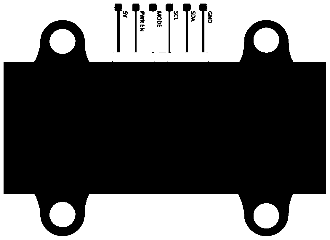
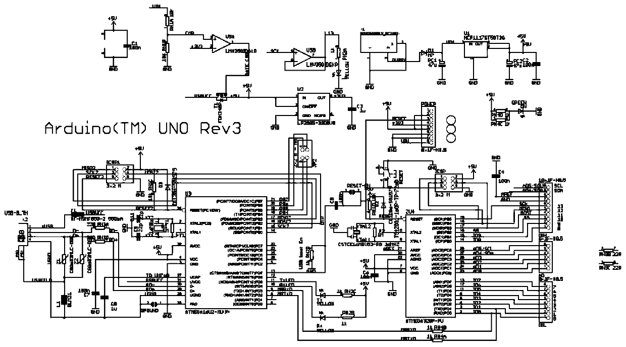
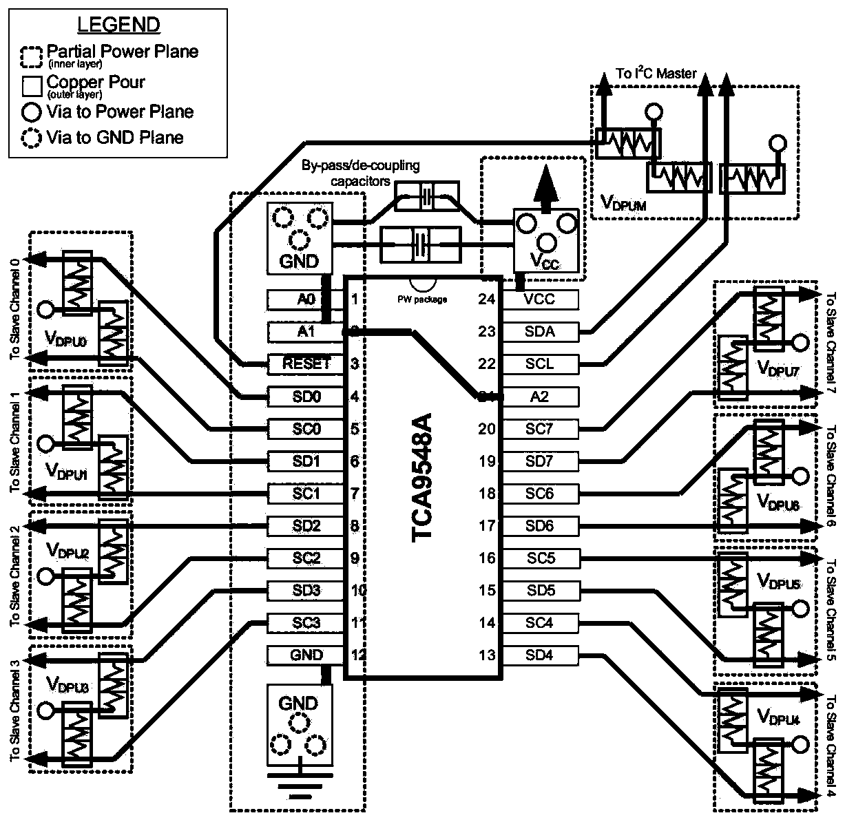

Image

  • Laser ranging-based road traffic monitoring device
  • Laser ranging-based road traffic monitoring device
  • Laser ranging-based road traffic monitoring device

Examples


Embodiment Construction

[0028] Embodiments of the present invention are described in detail below, examples of which are shown in the drawings, wherein the same or similar reference numerals denote the same or similar elements or elements having the same or similar functions throughout. The embodiments described below by referring to the figures are exemplary only for explaining the present invention and should not be construed as limiting the present invention.

[0029] Those skilled in the art will understand that unless otherwise stated, the singular forms "a", "an", "said" and "the" used herein may also include plural forms. It should be further understood that the word "comprising" used in the description of the present invention refers to the presence of said features, integers, steps, operations, elements and / or components, but does not exclude the presence or addition of one or more other features, Integers, steps, operations, elements, components, and / or groups thereof. It will be understoo...


PUM


Abstract

The invention provides a laser ranging-based road traffic monitoring device. The device includes an industrial personal computer, a processor and a laser sensor array; the laser sensor array is arranged on an overhead frame above the lanes of a road; laser light emitted by every two laser sensors is vertically emitted to the road surface of each lane so as to perform uninterrupted high-frequency ranging; the processor is connected with the laser sensors, judges the passage of a vehicle according to ranging data sent from the laser sensors to the processor, records a time point Tstart when thehead of the vehicle reaches a position where a first laser beam is located, and a time point Tend2 when the tail of the vehicle leaves the position where the first laser beam is located, and records atime point Tend1 when the head of the vehicle reaches a position where a second laser beam is located; and the industrial personal computer is connected with the processor, and calculates the height,length and speed of the vehicle according to the ranging data, the time point Tstart, the time point Tend2 and the time point Tend1 sent by the processor. The device of the invention works stably under various environmental conditions, can measure the height of the vehicle, can recognize the contour of the vehicle, and is beneficial to vehicle model classification and the identification of over-long and over-high vehicles.

Description

technical field [0001] The invention relates to the technical field of road traffic monitoring, in particular to a road traffic monitoring device based on laser ranging. Background technique [0002] With the integration of the global economy and the increase of car ownership year by year, the traffic accident rate caused by vehicles running on the road is also increasing sharply. One of the traffic accidents is speeding. In order to effectively curb the traffic accidents caused by speeding, the traffic management department has enabled the automatic detection system of motor vehicle speeding in the road speed limit area and mobile speed measurement. At present, the speed measurement error of the most commonly used motor vehicle speed measurement system by the traffic management department reaches 1km / h, although its error has met the requirements of JJG528-2004 "Motor Vehicle Radar Speed ​​Meter Verification Regulations" and JJG527-2007 "Motor Vehicle Speeding Automatic Mon...

Claims


Application Information

Patent Timeline
Patent Type & Authority Applications(China)
IPC IPC(8): G08G1/04G08G1/015
Inventor 朱思聪李向頔喻东晓胡瑞雪蓝清郭晓光史磊陈大豹刘文伟孙治中
Owner BEIJING JIAOTONG UNIV
Why Eureka
Try Eureka