Scanning mechanism for driving magnetron, magnetron source and magnetron sputtering device

A scanning mechanism and magnetron technology, applied in the directions of magnetron, sputtering coating, ion implantation coating, etc., can solve the problem of low service life of the whole set of mechanisms, and achieve easy control, high reliability and simple motion trajectory Effect

Active Publication Date: 2019-05-31
BEIJING NAURA MICROELECTRONICS EQUIP CO LTD
View PDF5 Cites 1 Cited by
  • Summary
  • Abstract
  • Description
  • Claims
  • Application Information

AI Technical Summary

Problems solved by technology

However, due to the belt transmission mechanism, it is necessary to adjust the tension regularly and replace the belt regularly, and the service life of the entire mechanism is relatively low.

Method used


Image

  • Scanning mechanism for driving magnetron, magnetron source and magnetron sputtering device
  • Scanning mechanism for driving magnetron, magnetron source and magnetron sputtering device
  • Scanning mechanism for driving magnetron, magnetron source and magnetron sputtering device

Examples


Embodiment Construction

[0069] Specific embodiments of the present invention will be described in detail below in conjunction with the accompanying drawings. It should be understood that the specific embodiments described here are only used to illustrate and explain the present invention, and are not intended to limit the present invention.

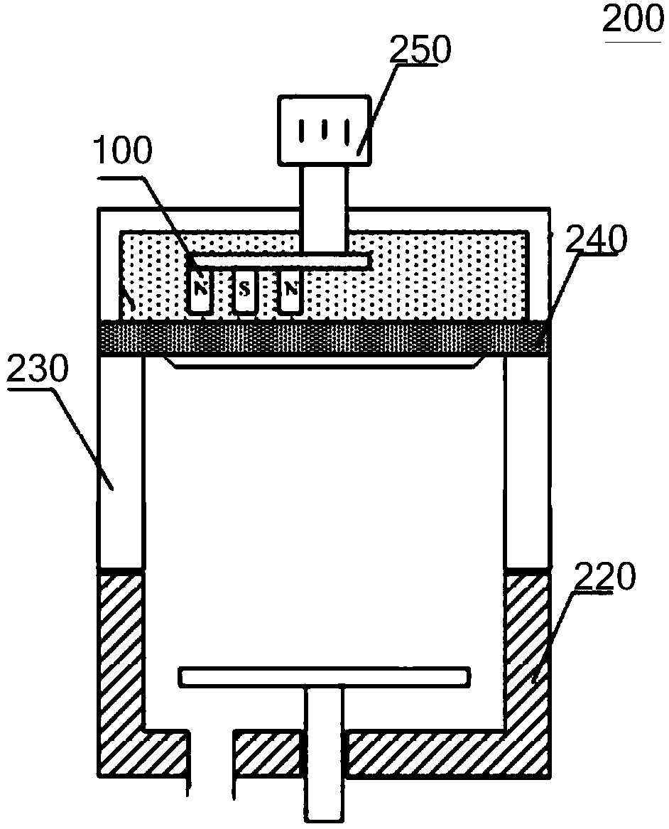
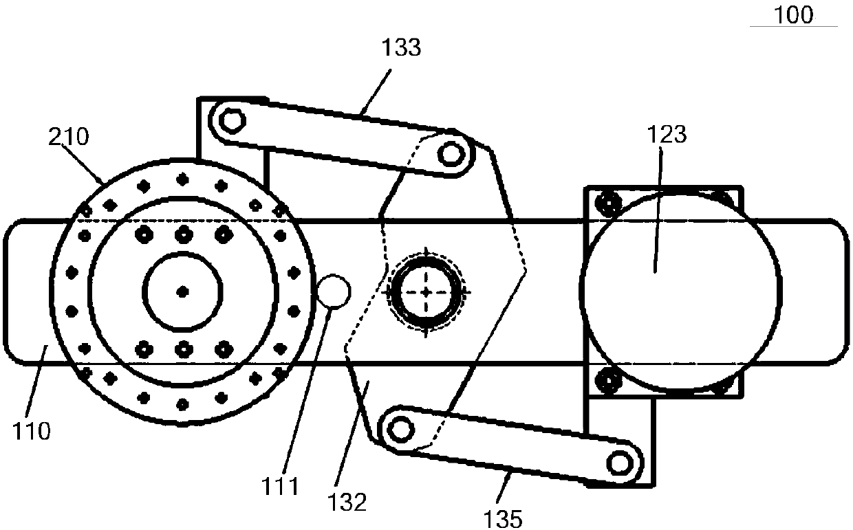
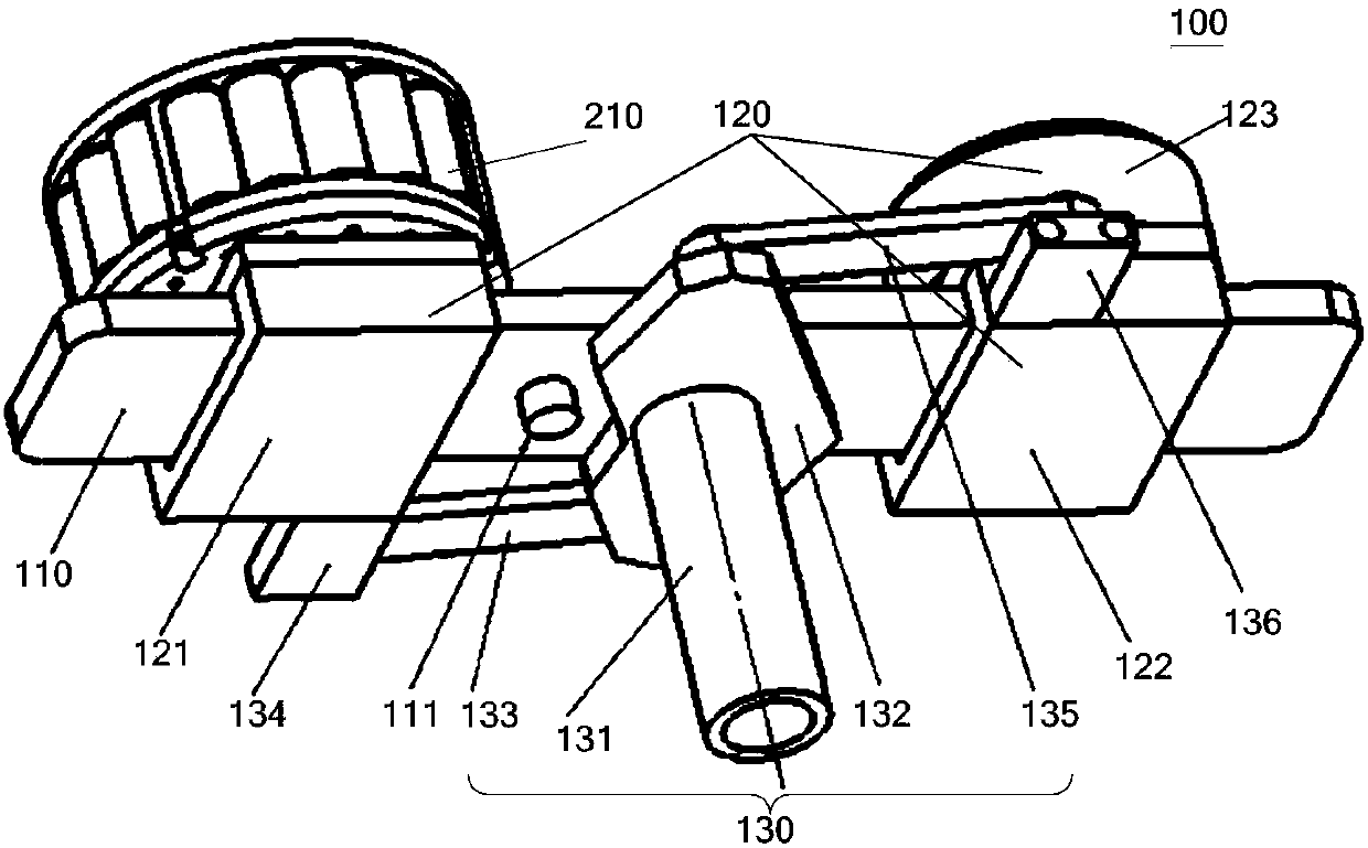
[0070] Such as figure 2 , image 3 , Figure 4 with Figure 5 As shown, the first aspect of the present invention relates to a scanning mechanism 100 for driving a magnetron, and the scanning mechanism 100 includes a guide rail 110 , a moving structure 120 and a driving assembly 130 . Wherein, a limiting member 111 is disposed on the guide rail 110 . The moving structure 120 is disposed on the guide rail 110 and can move back and forth along the guide rail 110 . The driving assembly 130 is rotatably arranged on the guide rail 110, and is used to drive the moving structure 120 to move to the first preset position or the second preset position on the guide r...


PUM


Abstract

The invention discloses a scanning mechanism for driving a magnetron, a magnetron source and a magnetron sputtering device. The scanning mechanism comprises a guide rail on which a stopping piece is arranged; a moving structure disposed on the guide rail and capable of reciprocating along the guide rail; a driving component rotatably disposed on the guide rail and used for moving the moving structure on the guide rail to a first predetermined position or second predetermined position and then rotating the moving structure around a target material central axis such that the magnetron is alignedto the edge region or the central region of the target material and then rotates around the target material central axis. Therefore, the scanning mechanism of the present invention is simple in motion trajectory, easy to control, and high in reliability when switching different positions of the magnetron, and can also be applied to various types of magnetrons.

Description

technical field [0001] The invention relates to the technical field of semiconductor manufacturing, in particular to a scanning mechanism for driving a magnetron, a magnetron source including the scanning mechanism and a magnetron sputtering device including the magnetron source. Background technique [0002] Magnetron sputtering or sputtering (Sputtering) deposition technology is a kind of physical vapor deposition (Physical Vapor Deposition, PVD), is the most widely used type of thin film manufacturing technology in the semiconductor industry, generally refers to the use of physical methods to prepare thin films Preparation Process. Physical vapor deposition technology can be applied to many process fields, such as copper interconnection technology, through silicon via (Through Silicon Via, TSV) technology in the packaging field, and so on. [0003] In recent years, with the development of technology, it has become possible to deposit films on the side walls of holes with...

Claims


Application Information

Patent Timeline
Patent Type & Authority Applications(China)
IPC IPC(8): H01J25/52C23C14/35
Inventor 赵康宁魏景峰
Owner BEIJING NAURA MICROELECTRONICS EQUIP CO LTD
Why Eureka
Try Eureka