Flywheel energy storage system

A flywheel energy storage and rotor technology, which is applied in the direction of controlling mechanical energy, electrical components, electromechanical devices, etc., can solve the problems of difficult to ensure the straightness of the axis and processing difficulty, and achieve the effects of reducing processing difficulty, increasing rotor speed, and avoiding crushing

Pending Publication Date: 2019-05-31
CHANGSHA UNIVERSITY OF SCIENCE AND TECHNOLOGY
View PDF5 Cites 2 Cited by
  • Summary
  • Abstract
  • Description
  • Claims
  • Application Information

AI Technical Summary

Problems solved by technology

When the length of the rotor shaft is large, it is difficult to ensure the straightness of the axis during processing. At the same time, it is difficult to maintain dynamic balance during high-speed rotation.

Method used


Image

  • Flywheel energy storage system
  • Flywheel energy storage system
  • Flywheel energy storage system

Examples


Embodiment Construction

[0015] The present invention will be described in detail below in conjunction with the accompanying drawings and embodiments.

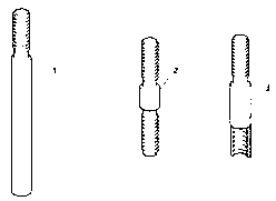
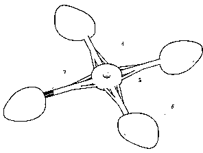
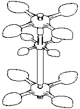
[0016] 1. Reference Figure 1 to Figure 2 , a flywheel energy storage system rotor of the present invention includes a lower rotor shaft 2, an upper rotor shaft 3, a hub 4, and a spoke 5; the lower rotor shaft 2 and a plurality of upper rotor shafts 3 are connected together to form a whole rotor shaft 1; the hub 4 is connected to the upper part of the lower rotor shaft 2 or the upper rotor shaft 3 .

[0017] Both ends of the lower rotor shaft 2 are protruding threads, and the lower part of the upper rotor shaft 3 is a concave thread and the upper part is a protruding thread. The hub 4 is connected to the upper protruding thread of the lower rotor shaft 2 or the upper rotor shaft 3 by a screw, and the screw direction is just in time to generate a tightening force when the flywheel rotates. After the wheel hub 4 is tightened, the upper rotor shaft is ...


PUM


Abstract

The invention discloses a flywheel energy storage system rotor comprising a lower rotor shaft, upper rotor shafts, a hub and a spoke. The lower rotor shaft and the plurality of upper rotor shafts areconnected together to form an integrated rotor shaft. The hub is connected to the lower rotor shaft or the upper parts of the upper rotor shafts. Such design uses multiple spirally-connected rotor shafts, and greatly reduces the machining difficulty. Each rotor shaft carries a flywheel block to maintain the energy density. The cooperation of the flywheel block with the segmented rotor avoids a breaking risk under centrifugal force and is beneficial to an increase in rotor speed.

Description

technical field [0001] The invention relates to a flywheel energy storage system rotor, in particular to a segmented flywheel energy storage system rotor. Background technique [0002] The stability requirements of the power grid bring development opportunities for energy storage. Wind-solar facilities, peak shaving and flat valleys, and electric vehicles will become new drivers for the rapid development of energy storage. The domestic energy storage market has created a market space of 100 billion yuan. Flywheel energy storage Compared with chemical batteries, flywheel batteries have the characteristics of high specific energy, long life (up to more than 25 years), fast charging and discharging, no pollution, and maintenance-free. The mechanical flywheel in the flywheel energy storage system is mostly made in the form of a full circle. When it rotates with the rotor at high speed, it will generate a large radial and circumferential tension due to the huge centrifugal force....

Claims


Application Information

Patent Timeline
Patent Type & Authority Applications(China)
IPC IPC(8): H02J3/30H02K7/02
CPCY02E60/16
Inventor 廖力达谭奇张柳江
Owner CHANGSHA UNIVERSITY OF SCIENCE AND TECHNOLOGY
Why Eureka
Try Eureka