Assembly structure of automobile reduction gearbox body and motor shaft

An assembly structure and motor shaft technology, which is applied in the direction of electromechanical devices, electrical components, mechanical equipment, etc., can solve the problems of motor shaft movement, vibration and noise, and affect the NVH performance of automobiles, so as to achieve stable assembly structure and reduce vibration and noise , The effect of improving NVH performance

Pending Publication Date: 2019-05-31
CHONGQING TSINGSHAN IND
View PDF0 Cites 1 Cited by
  • Summary
  • Abstract
  • Description
  • Claims
  • Application Information

AI Technical Summary

Problems solved by technology

However, the motor shaft assembled in this way will be affected by the bearing clearance. During the working process, the motor shaft will move axially, resulting in vibration and noise, which will affect the NVH performance of the car.

Method used


Image

  • Assembly structure of automobile reduction gearbox body and motor shaft
  • Assembly structure of automobile reduction gearbox body and motor shaft
  • Assembly structure of automobile reduction gearbox body and motor shaft

Examples


Embodiment 1

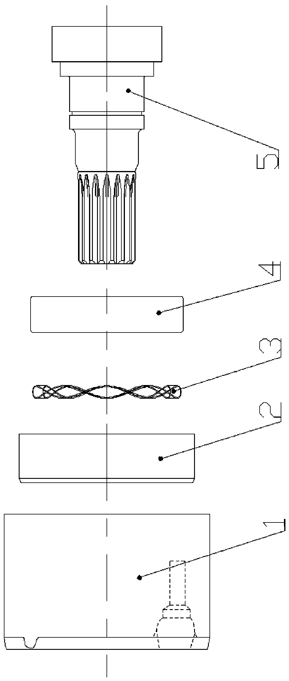
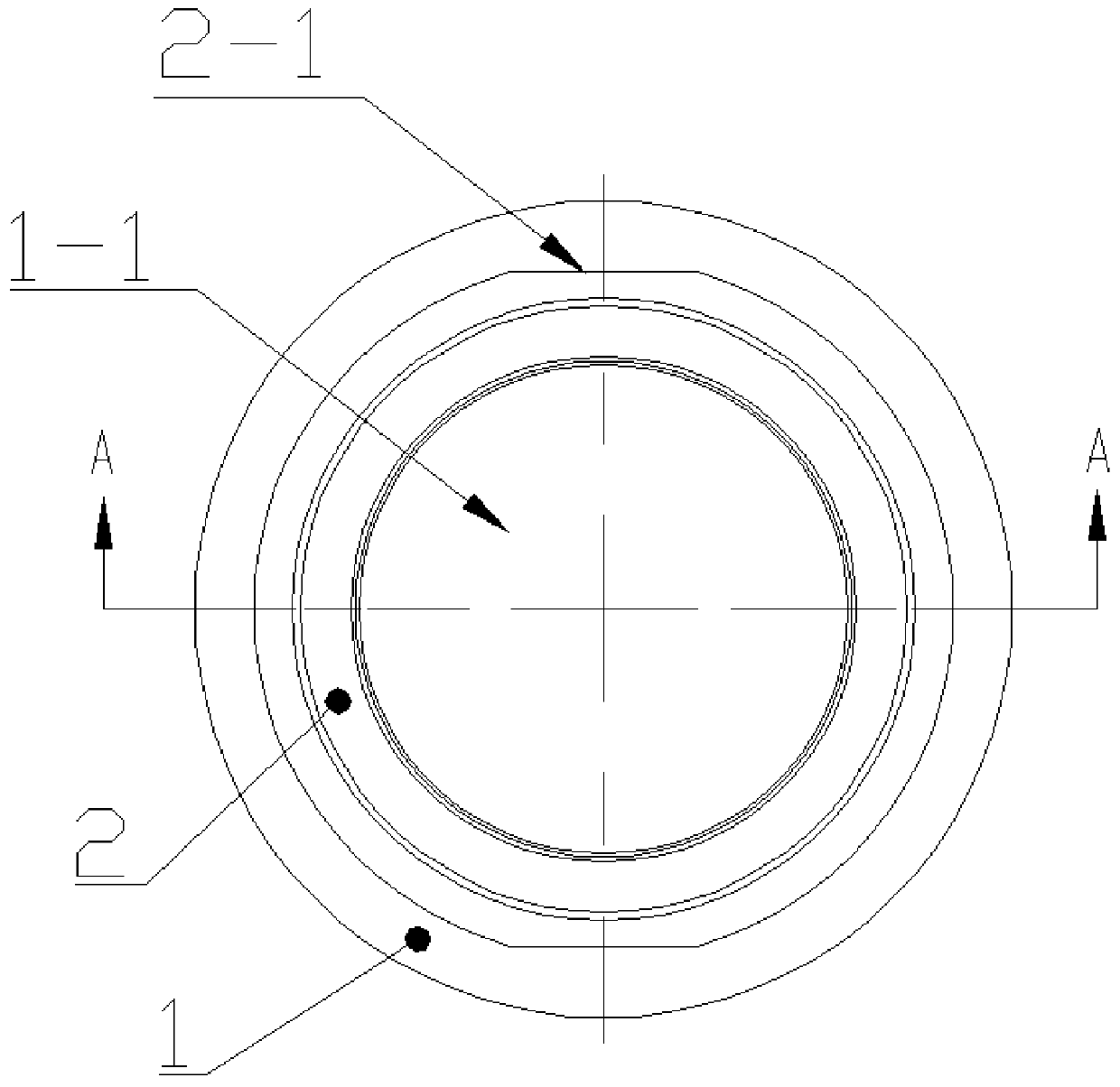
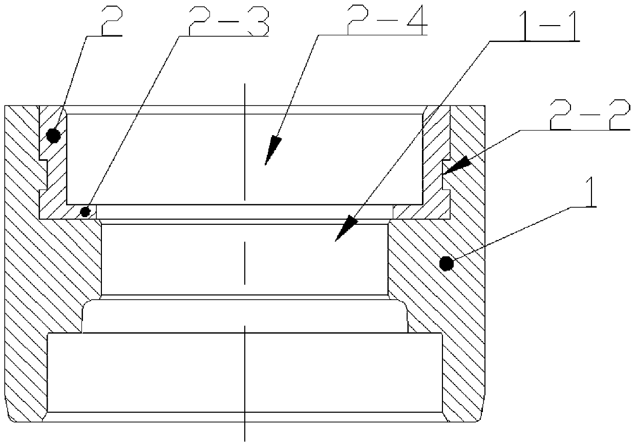
[0020] Embodiment one, see Figure 1 to Figure 3 , an assembly structure of an automobile gear box body and a motor shaft, comprising a box body 1 of the gear box and a motor shaft 5, the box body 1 is molded by aluminum water die-casting, and the motor shaft 5 is equipped with a bearing 4 and an inner part of the bearing 4 The ring is matched, and the end of the motor shaft 1 is provided with a spline for installing the power input gear of the reduction box. The box body 1 is provided with a step hole 1-1, and the step hole 1-1 is located in the large-diameter hole at the outer end of the box body 1. A steel sleeve 2 is fixed, and the steel sleeve 2 is against the shaft of the step hole 1-1. Shoulder, the shaft shoulder axially limited one end of the steel sleeve 2. The outer circumference of the steel sleeve 2 is symmetrically provided with a tangential plane 2-1 for two-way limit, the outer circumference of the steel sleeve 2 is provided with an axial limit groove 2-2, and...

Embodiment 2

[0021] Embodiment two, such as Figure 4 , Figure 5 , its basic structure is the same as that of Example 1, the difference is that the steel sleeve 2 is fixed in the large-diameter hole of the stepped hole 1-1 of the box body 1 through cold press interference fit, and the steel sleeve 2 and the box body 1 The outer end of the stepped hole 1-1 is evenly distributed on the outer end of the stepped hole 1-1. There are three saddle holes 6. Each saddle hole 6 is a blind hole arranged in the axial direction. Each saddle hole 6 is interference-fitted with a stop pin 7 pairs of steel pins. Set 2 circumferential and axial limit. The three seam holes 6 can realize the stable limit of the steel sleeve 2. The cold press interference fit assembly between the steel sleeve 2 and the box body 1 is simple, and the blind hole 6 and the stop pin 7 together form a pair of steel sleeves. 2, even if the steel sleeve 2 and the box body 1 become loose due to heat, the stable connection between th...


PUM


Abstract

The invention relates to an assembly structure of an automobile reduction gearbox body and a motor shaft. The assembly structure comprises a reduction gearbox body and the motor shaft, wherein the motor shaft is provided with a bearing and matches the inner ring of the bearing; the box body is provided with a stepped hole; a steel sleeve is fixed in the large-diameter hole of the stepped hole; thesteel sleeve is abutted against the shoulder of the stepped hole; the outer ring of the bearing is in clearance fit with the shaft hole of the steel sleeve; one end of the steel sleeve abutted against the shoulder of the stepped hole is provided with a flange extending toward a shaft center; a wave spring for compensating a bearing clearance is disposed between the flange and the outer ring of the bearing; and the end portion of the motor shaft extends into the cavity of the box body from the small-diameter hole of the stepped hole. The assembly structure is stable, firm in connection betweenthe steel sleeve and the reduction box body, avoids the axial movement of the motor shaft, and reduces vibration and noise.

Description

technical field [0001] The invention relates to the field of assembly of automobile parts, in particular to an assembly structure of an automobile reduction box body and a motor shaft. Background technique [0002] The motor of the car outputs power through the motor shaft, but due to the high speed of the motor shaft, it usually cannot be used to directly drive the car, but needs to be decelerated by a gearbox before outputting the power. At present, the motor shaft and the casing of the reduction box usually support the motor shaft on the casing of the reduction box through bearings, and the supported bearings are directly installed in the mounting holes provided on the casing of the reduction box. However, the motor shaft assembled in this way will be affected by the bearing clearance. During the working process, the motor shaft will move axially, resulting in vibration and noise, which affects the NVH performance of the car. Contents of the invention [0003] The purp...

Claims


Application Information

Patent Timeline
Patent Type & Authority Applications(China)
IPC IPC(8): H02K7/10F16H57/022
Inventor 肖成加蔡之骏杨毅超藏迎青吴守国
Owner CHONGQING TSINGSHAN IND
Why Eureka
Try Eureka