Linear motor position feedback device

A linear motor and feedback device technology, applied in the direction of electromechanical devices, electrical components, electric components, etc., can solve the problems of high temperature, dust, oil pollution, difficult installation, difficult production and other problems, and achieve great practical value and economy Benefits, guaranteed reliability and applicability, high anti-pollution level effect

Pending Publication Date: 2019-05-31
SUZHOU LINGHOU ROBOT
View PDF0 Cites 5 Cited by
  • Summary
  • Abstract
  • Description
  • Claims
  • Application Information

AI Technical Summary

Problems solved by technology

At present, in the linear motor system, optical sensing or magnetic induction is mainly used as the position feedback method of the mover. The optical sensing position feedback device is mainly composed of a grating ruler and an optical encoder reading head, and the accuracy is high. However, due to the production process, The measuring length is limited. The longer the length of the grating ruler, the more difficult it is to manufacture and the higher the cost. It is mostly suitable for a stroke of less than 2m, and it is greatly affected by temperature, dust, and oil, and it is more difficult to install.
The magnetic induction position feedback device is mainly composed of a magnetic scale and a magnetic encoder reading head. When it works, it will generate a lot of noise. There are technical requirements for installation, and the longer the linear motor, the longer the magnetic scale, which will increase the cost.

Method used


Image

  • Linear motor position feedback device
  • Linear motor position feedback device
  • Linear motor position feedback device

Examples


Embodiment Construction

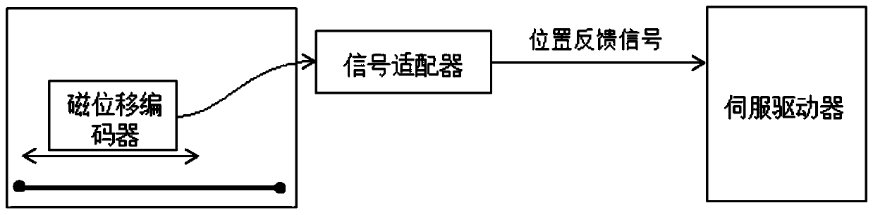
[0030] Such as figure 1 As shown, the linear motor position feedback device of the present invention includes a magnetic displacement encoder, a signal adapter and a connecting wire; the magnetic displacement encoder, the signal adapter and the servo driver are sequentially connected through a connecting wire.

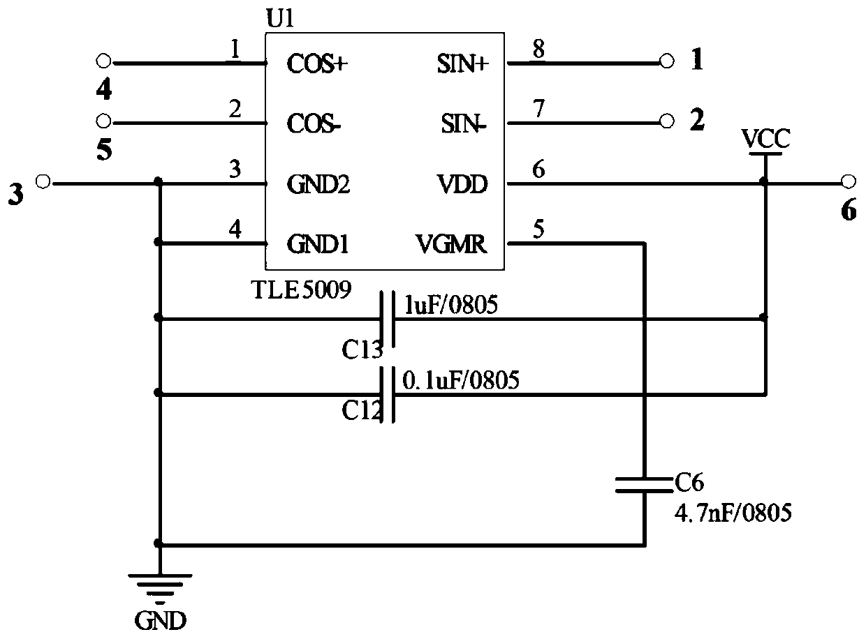
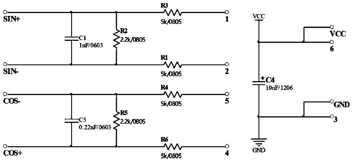
[0031] The magnetic displacement encoder is glued into the encoder mechanism, and the encoder mechanism is installed on the mover of the linear motor, and follows the movement of the mover to detect the change of the magnetic field of the stator of the linear motor in real time; Figure 2-3 As shown, the magnetic displacement encoder includes a first PCB board and a second PCB board inside, and the first PCB board and the second PCB board are respectively covered with a reluctance magnetic field detection circuit and an analog sin-cosine signal output circuit; the first PCB board A reluctance chip is integrated on the board to detect the magnetic field of the linear mo...


PUM


Abstract

The invention discloses a linear motor position feedback device which comprises a magnetic displacement encoder, a signal adapter and a connecting line which are connected via a connecting line. The magnetic displacement encoder comprises a magnetic resistance and magnetic field detection circuit and an analog sine/cosine signal output signal connected successively, and the signal adapter comprises a refining circuit, and a power supply circuit, an external EEPROM storage circuit, an SPI serial debugging interface circuit, an error state indication circuit, an amplitude phase calibration circuit and a differential driving circuit connected to the refining circuit. A magnetic resistance chip is used to detect magnetic field change and output an analog sine/cosine signal, analog-to-digital conversion, refining and difference output are carried out on the analog sine/cosine signal, the signal is fed back to a servo driver, the linear motor position is detected, both a grating and a magnetic railing ruler are omitted, the structure is simple, installation is convenient, there is no friction due the non-contact manner, the anti pollution level is high, and the cost is reduced greatly.

Description

technical field [0001] The invention relates to motor position detection, in particular to a linear motor position feedback device. Background technique [0002] With the advancement of science and technology and the improvement of automation level, linear motors, as a transmission device that directly converts electrical energy into linear motion mechanical energy, have been widely used in the field of automatic control. Domestic research on linear motors and their servo drive systems Also step by step. At present, in the linear motor system, optical sensing or magnetic induction is mainly used as the position feedback method of the mover. The optical sensing position feedback device is mainly composed of a grating ruler and an optical encoder reading head, and the accuracy is high. However, due to the production process, The measurement length is limited. The longer the length of the grating ruler, the more difficult it is to manufacture and the higher the cost. It is mos...

Claims


Application Information

Patent Timeline
Patent Type & Authority Applications(China)
IPC IPC(8): H02K11/215
Inventor 谢子阳孟健张德伟柳刚王德保
Owner SUZHOU LINGHOU ROBOT
Why Eureka
Try Eureka