Forming device for sand casting cavity

A molding device and sand casting technology, which is applied in the field of sand casting, can solve the problems of poor sand core effect, inability to lay uniformly, poor sand core forming effect, etc., and achieve high processing efficiency

Active Publication Date: 2019-06-04
LINYI TIANKUO CASTING CO LTD
View PDF9 Cites 6 Cited by
  • Summary
  • Abstract
  • Description
  • Claims
  • Application Information

AI Technical Summary

Problems solved by technology

[0003] The publication number is CN105834377B, which provides a fully automatic sand box molding equipment. This device uses direct injection sand filling. This sand filling method cannot be laid evenly after the molding sand falls in the sand box, and then the sand core is formed during subsequent compaction. The effect is not good, and the effect of the sand core after subsequent processing is not good

Method used


Image

  • Forming device for sand casting cavity
  • Forming device for sand casting cavity
  • Forming device for sand casting cavity

Examples


Embodiment

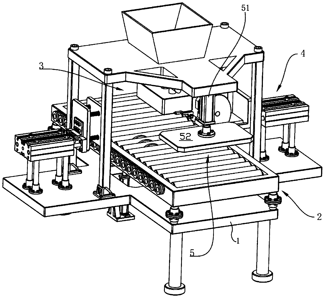
[0028] see Figure 1 to Figure 6 , the present invention provides a technical solution:

[0029] A cavity forming device for sand casting, comprising a frame 1, a conveying mechanism 2, a sand output mechanism 3, a shaking mechanism 4 and a compacting mechanism 5, wherein:

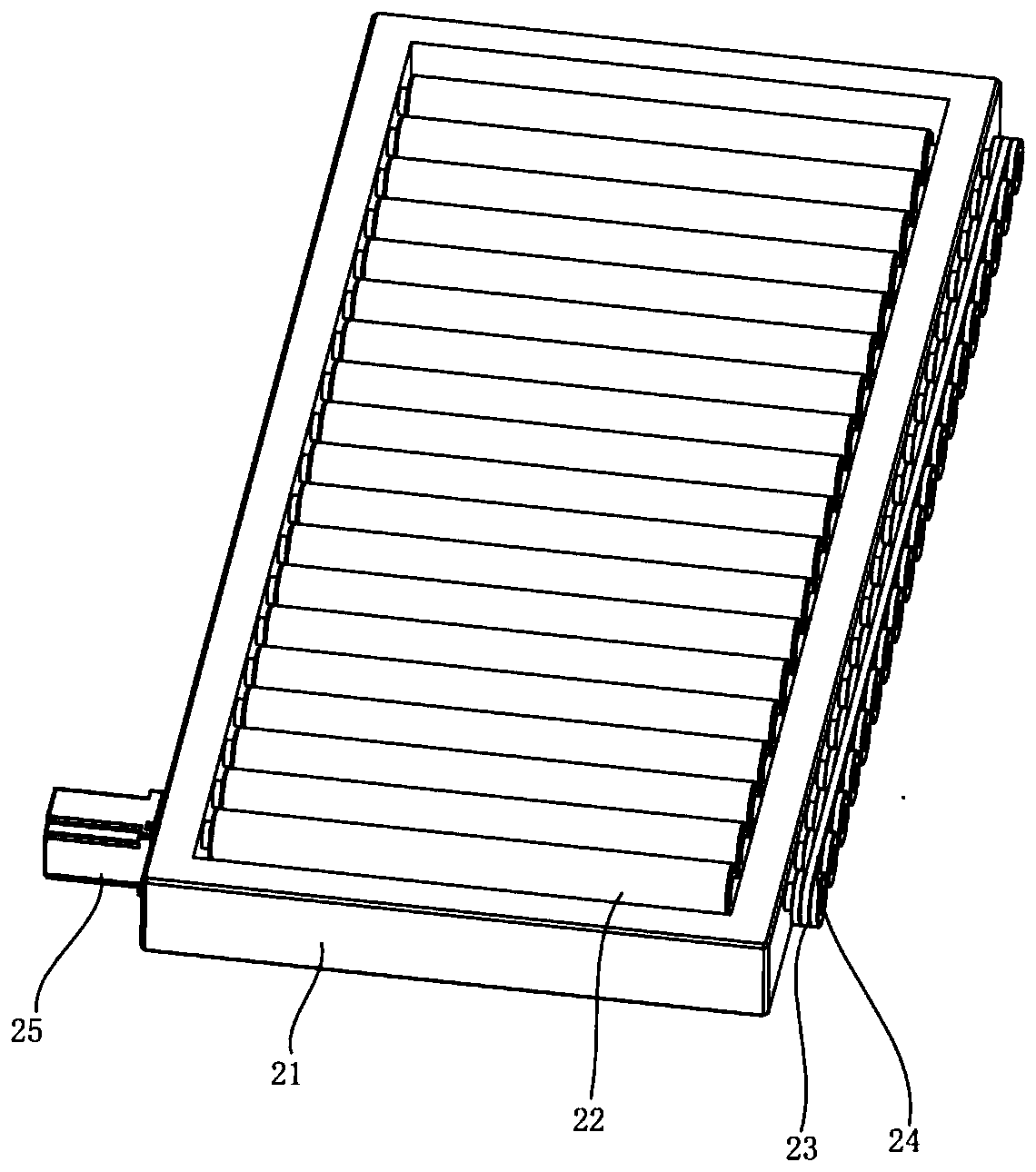
[0030] Conveyor mechanism 2 comprises support 21, rubber roller 22, pulley 23, belt 24 and reduction motor 25, and support 21 is fixedly installed on the frame 1 and is positioned at the below of discharge box 32, and several rubber rollers 22 are equidistantly installed on In the bracket 21, a pulley 23 is sheathed on the rubber roller 22, and the belt 24 is sleeved on several pulleys 23. The reduction motor 25 is fixed on the bracket 21 through bolts, and the power output end of the reduction motor 25 is connected to one of the rubber rollers. 22 are fixedly connected by a coupling;

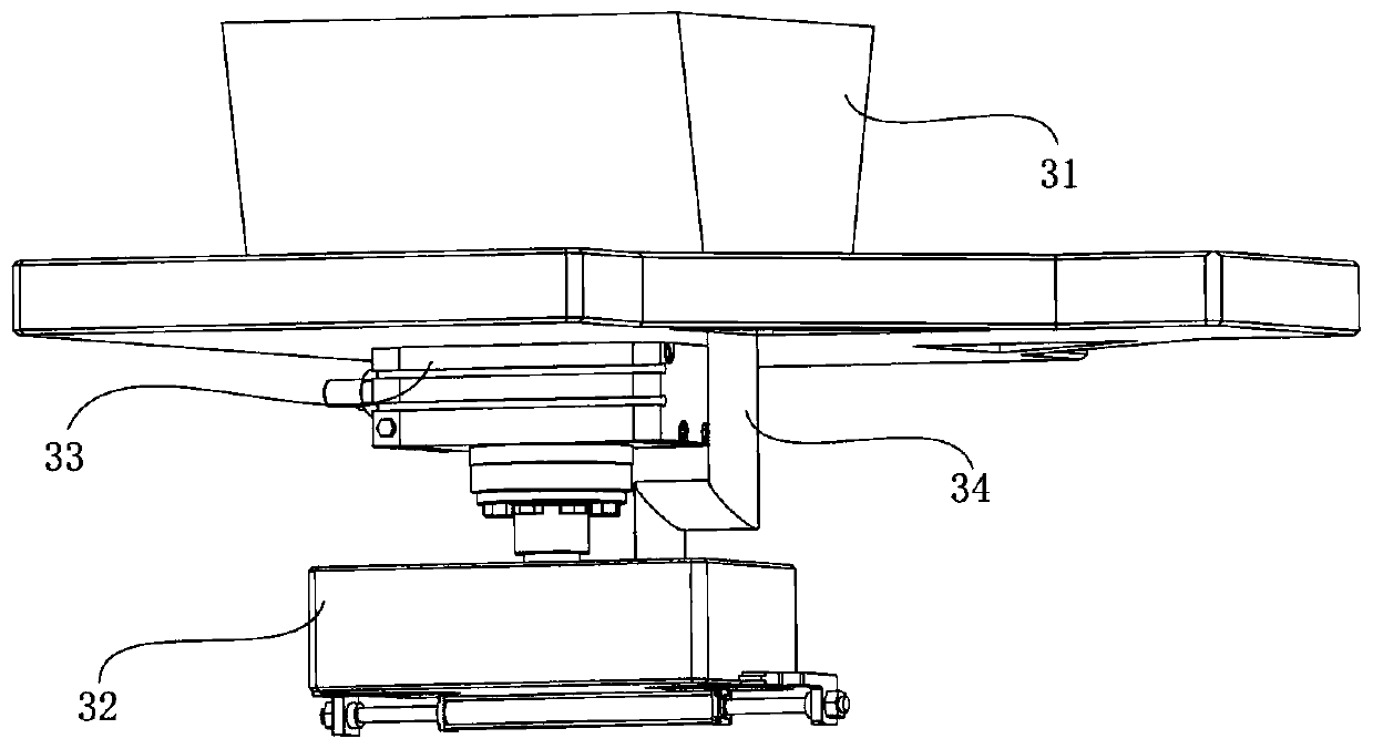
[0031] The sand outlet mechanism 3 includes a hopper 31, a discharge box 32, a rotary cylinder 33, a telescopic hose 34...


PUM


Abstract

The invention provides a forming device for a sand casting cavity. The forming device comprises a machine frame, a conveying mechanism, a sand discharging mechanism, a material shaking mechanism and acompacting mechanism; the sand discharging mechanism comprises a feeding hopper, a discharging box, a rotary cylinder, an elastic hose, two drawing plates and a dual-direction cylinder, the discharging box is installed on the upper layer plate of the machine frame through the rotary cylinder, the discharging box communicates with the feeding hopper through the elastic hose, the two drawing platesare separately installed at the bottom of the discharging box in a movable mode, discharging holes are formed in the drawing plates; and the ends, provided with the discharging holes, of the drawingplates extend into the discharging box, the two drawing plates are correspondingly and fixedly connected to power output ends at the two ends of the dual-direction cylinder, and the material shaking device is installed on the machine frame. The discharging box is driven to rotate back and forth by the rotary cylinder, the drawing plates are driven to move back and forth by the dual-direction cylinder, so that when discharging is performed, the positions of the discharging holes relative to the side edge of the discharging box are changed constantly, forming sand are uniformly laid in a sand box when sand discharging is performed, and the forming sand is enabled to be more tight.

Description

technical field [0001] The invention relates to the technical field of sand casting, in particular to a cavity forming device for sand casting. Background technique [0002] Steel, iron and most non-ferrous alloy castings can be obtained by sand casting. In the process of sand casting, sand needs to be injected into the cavity and compacted to form a core for casting processing. [0003] The publication number is CN105834377B, which provides a fully automatic sand box molding equipment. This device uses direct injection sand filling. This sand filling method cannot be laid evenly after the molding sand falls in the sand box, and then the sand core is formed during subsequent compaction. The effect is not good, and then the effect of the sand core processed subsequently is not good. Contents of the invention [0004] The object of the present invention is to provide a cavity forming device for sand casting to solve the problems raised in the above-mentioned background tech...

Claims


Application Information

Patent Timeline
Patent Type & Authority Applications(China)
IPC IPC(8): B22C15/30
Inventor 吴义成任晨耿洪玲
Owner LINYI TIANKUO CASTING CO LTD
Why Eureka
Try Eureka