Supercharge Your Innovation With Domain-Expert AI Agents!

Positioning device and method for machining gland sealing arc segment in steam turbine

The technology of a positioning device and a positioning method, which is applied in the field of steam turbine parts, can solve the problem that the positioning device cannot meet the processing and positioning of various types of steam seal arcs, and achieve the effect of simple structure, low manufacturing cost and strong versatility

Pending Publication Date: 2019-06-04
HARBIN TURBINE
View PDF0 Cites 5 Cited by
  • Summary
  • Abstract
  • Description
  • Claims
  • Application Information

AI Technical Summary

Problems solved by technology

[0003] The technical problem to be solved in the present invention is: the existing positioning device for the seal arc section cannot meet the processing and positioning of various types of seal arc sections, and then provides a positioning device and positioning device for processing the steam seal arc section in the steam turbine method

Method used


Image

  • Positioning device and method for machining gland sealing arc segment in steam turbine
  • Positioning device and method for machining gland sealing arc segment in steam turbine
  • Positioning device and method for machining gland sealing arc segment in steam turbine

Examples


specific Embodiment approach 1

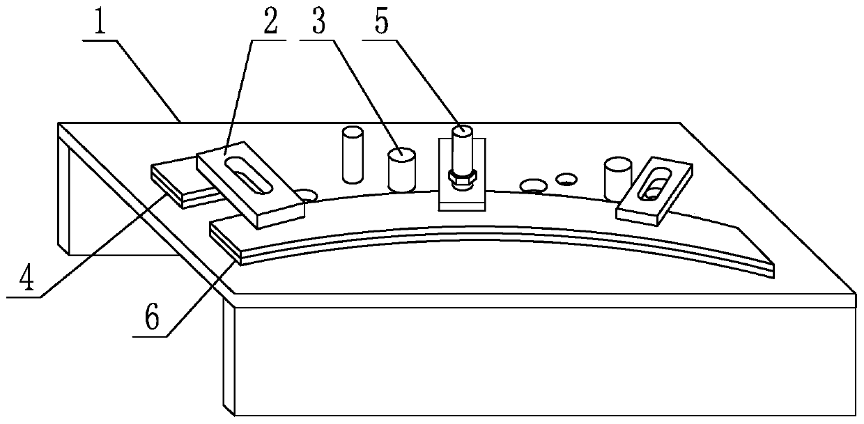
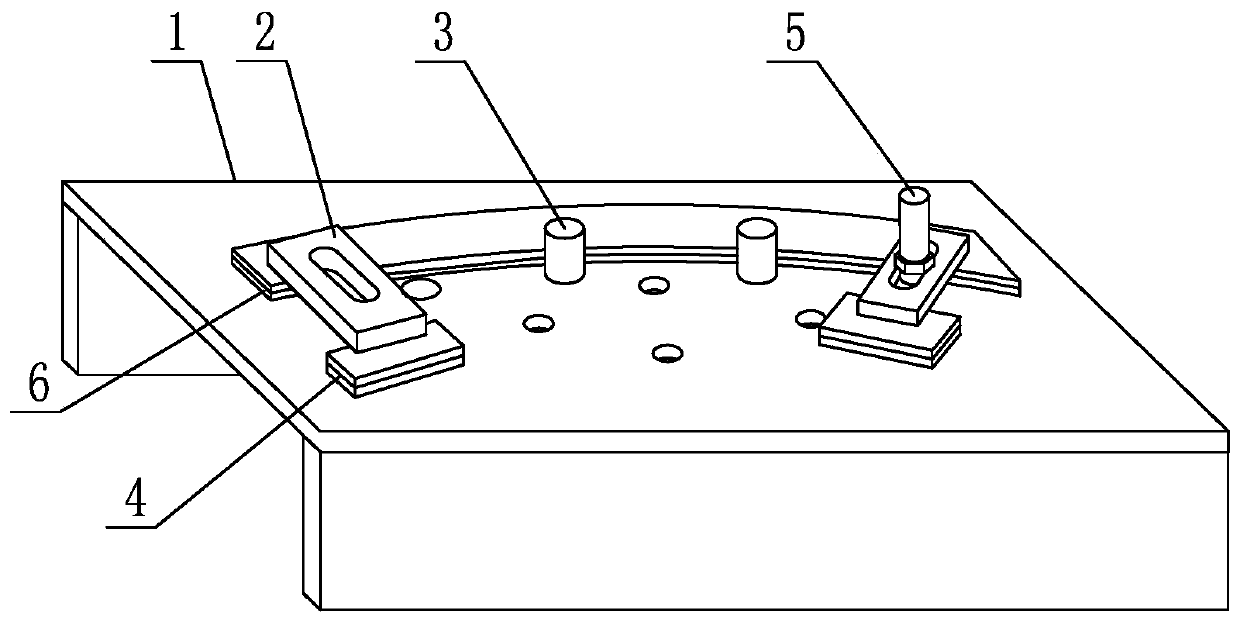
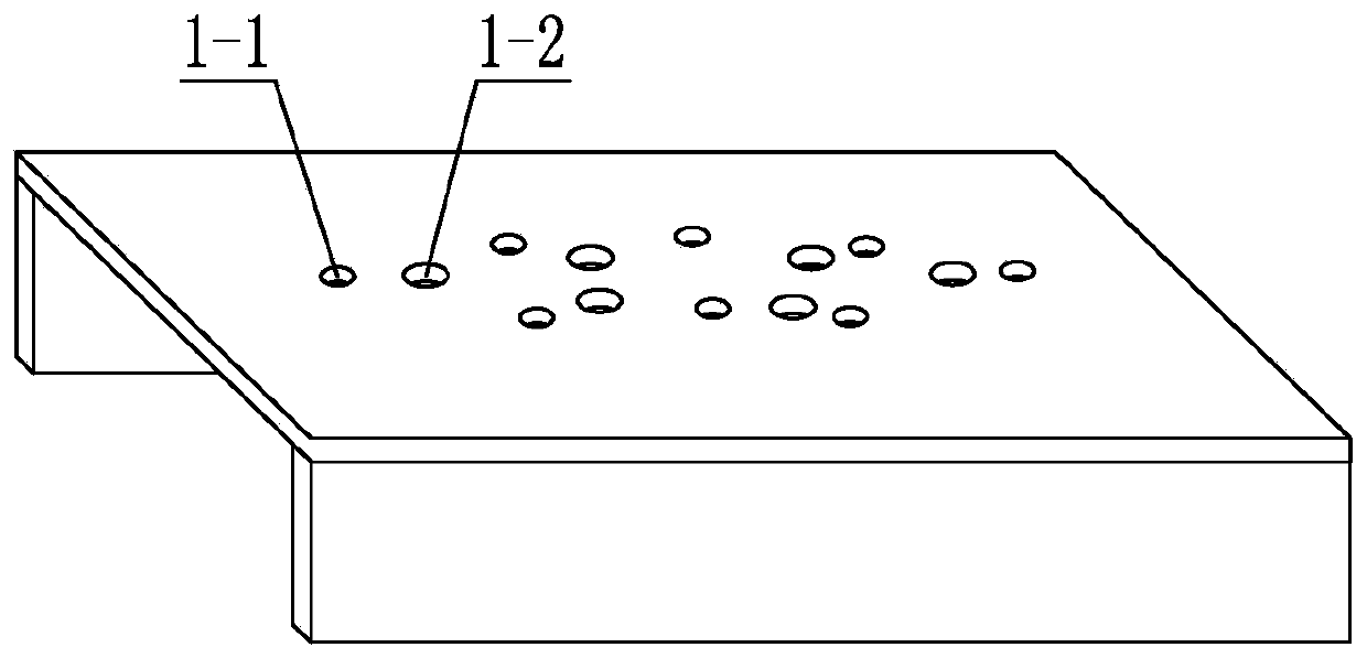
[0025] Specific implementation mode one: as figure 1 and figure 2 As shown, the positioning device described in this embodiment includes a workbench 1, a plurality of pressing plates 2, a plurality of positioning pins 3, a plurality of gaskets 4 and a plurality of compression bolts 5, such as image 3 As shown, there are a plurality of bolt holes 1-1 and a plurality of positioning holes 1-2 on the table of the workbench 1, and a plurality of bolt holes 1-1 and a plurality of positioning holes 1-2 are evenly distributed throughout the work On the table of platform 1, it is beneficial to the positioning and clamping of different types of steam seal arcs,

[0026] Such as Figure 5 As shown, in order to facilitate the adjustment of the position of the pressure plate, a long strip-shaped chute 2-1 is opened on the pressure plate 2 along the length direction of the pressure plate 2, and the pressure plate 2 is fixed and installed on the table top of the workbench 1 through the c...

specific Embodiment approach 2

[0030] Specific implementation mode two: as Image 6 As shown, a threaded column 3-1 is provided on one end surface of the positioning pin 3 described in this embodiment, and the threaded column 3-1 is screwed into the positioning hole 1-2, and the axis of the threaded column 3-1 is aligned with the positioning pin 3. The axes are coincident or parallel.

[0031] Other composition and connection methods are the same as those in Embodiment 1.

specific Embodiment approach 3

[0032] Specific implementation mode three: as Figure 4 As shown, the positioning device described in this embodiment further includes an arc-shaped gasket 6 , and the arc-shaped gasket 6 is placed on the table top of the workbench 1 . The arc gasket 6 can be used to adjust the height of the steam seal arc section.

[0033] Other composition and connection methods are the same as those in Embodiment 2.


PUM


Abstract

The invention discloses a positioning device and method for machining a gland sealing arc segment in a steam turbine, and relates to parts of the steam turbine. An existing gland sealing arc segment positioning device cannot meet machining and positioning of various types of gland sealing arc segments. The positioning device comprises a worktable, a plurality of pressing plates, a plurality of positioning pins, a plurality of gaskets and a plurality of compressing bolts, a plurality of bolt holes and a plurality of positioning holes are formed in the table face of the worktable and evenly distributed in the table face of the whole worktable, long-strip-shaped sliding grooves are formed in the pressing plates in the length directions of the pressing plates, the pressing plates are fixedly mounted on the table face of the worktable through the compressing bolts, the positioning pins are mounted in the positioning holes in an inserted mode, and the gaskets are arranged at the bottom endsof the pressing plates. The positioning device and method are used for positioning of the gland sealing arc segment.

Description

technical field [0001] The invention relates to steam turbine parts, in particular to a positioning device and a positioning method for processing the inner steam seal arc section of a steam turbine. Background technique [0002] The internal working state of the steam turbine unit is high-speed operation. After the flow measurement of the final assembly unit, it is usually necessary to carry out precise calculation and high-precision repair of the flow size. The radial and axial dimensions of the sealing arc section are processed, and the repairing and repairing of the steam sealing arc section is generally processed by an ordinary CNC milling machine, which makes it necessary to temporarily compile the corresponding CNC program for processing different types of steam sealing arc sections, and equip and install corresponding tooling Fixtures consume too much time and reduce the efficiency of the general assembly. At present, the types of seal arcs of various types of units ...

Claims


Application Information

Patent Timeline
IPC IPC(8): B23Q3/06
Inventor 马铭阳黄揆孙海博张树纲刘雷张海军李明郭凤桐刘尚
Owner HARBIN TURBINE
Features
  • R&D
  • Intellectual Property
  • Life Sciences
  • Materials
  • Tech Scout
  • Unparalleled Data Quality
  • Higher Quality Content
  • 60% Fewer Hallucinations
Learn More