Rotary clamping manipulator based on automatic module control

A technology of module control and manipulator, which is applied in the direction of program control manipulator, manipulator, chuck, etc., can solve the problems of unfavorable repair and maintenance, high production cost, and difficulty in controlling the strength of the manipulator arm, and achieves simple and practical operation, low production cost and excellent structure simple effect

Inactive Publication Date: 2019-06-07
郎露枫
View PDF9 Cites 6 Cited by
  • Summary
  • Abstract
  • Description
  • Claims
  • Application Information

AI Technical Summary

Problems solved by technology

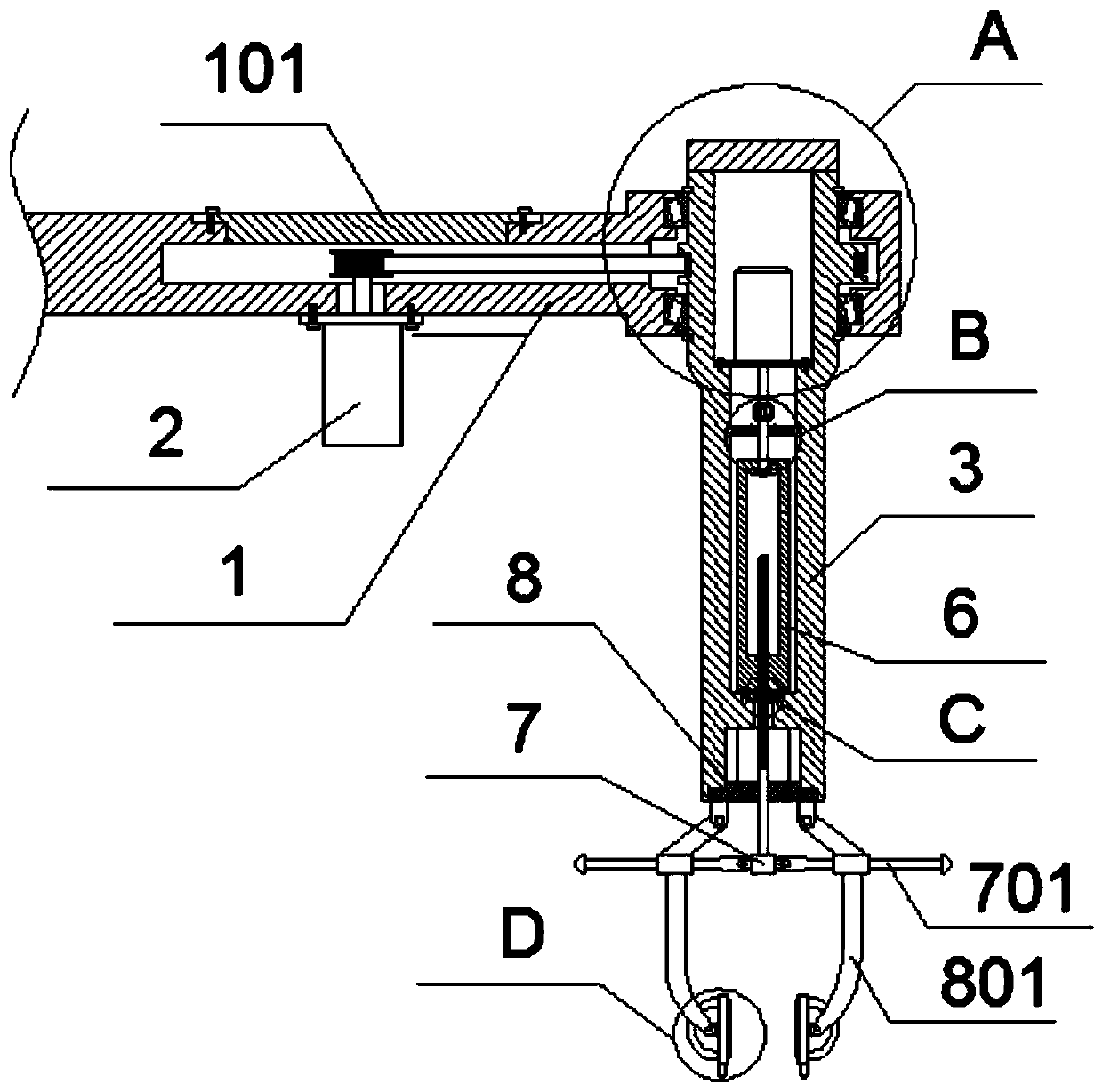
[0007] To sum up, the present invention provides a rotary clamping manipulator based on automation module control. Through structural and functional improvements, it solves the problem that the currently mainly used mechanical arm mainly clamps and lifts goods through air pressure and other methods. The streng

Method used


Image

  • Rotary clamping manipulator based on automatic module control
  • Rotary clamping manipulator based on automatic module control
  • Rotary clamping manipulator based on automatic module control

Examples


Example Embodiment

[0032] The embodiments of the present invention will be described in further detail below in conjunction with the drawings and examples. The following examples are used to illustrate the present invention, but cannot be used to limit the scope of the present invention.

[0033] In the description of the present invention, unless otherwise specified, "plurality" means two or more; the terms "upper", "lower", "left", "right", "inner", "outer" , "Front", "Back", "Head", "Tail", etc. indicate the orientation or positional relationship based on the orientation or positional relationship shown in the drawings, and are only for the convenience of describing the present invention and simplifying the description, not It is indicated or implied that the pointed device or element must have a specific orientation, be configured and operated in a specific orientation, and therefore cannot be understood as a limitation of the present invention. In addition, the terms "first", "second", "third...


PUM


Abstract

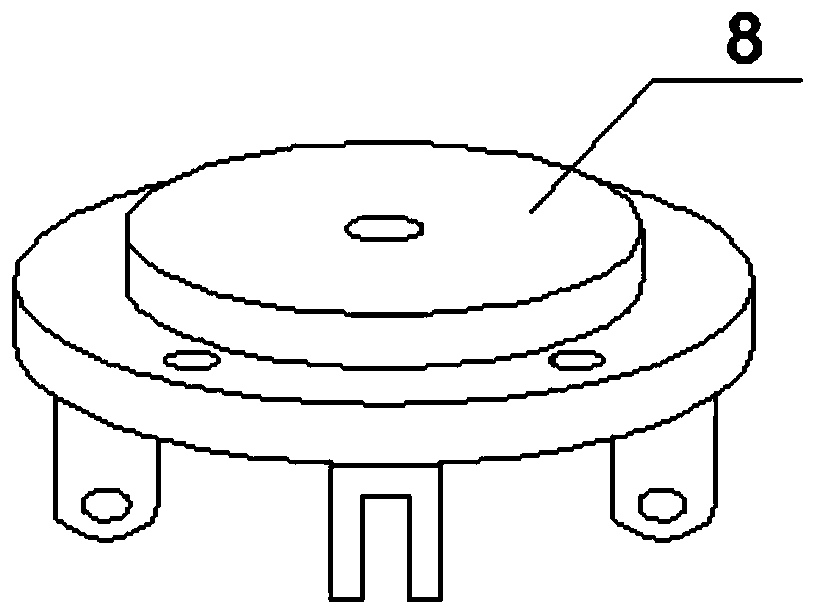
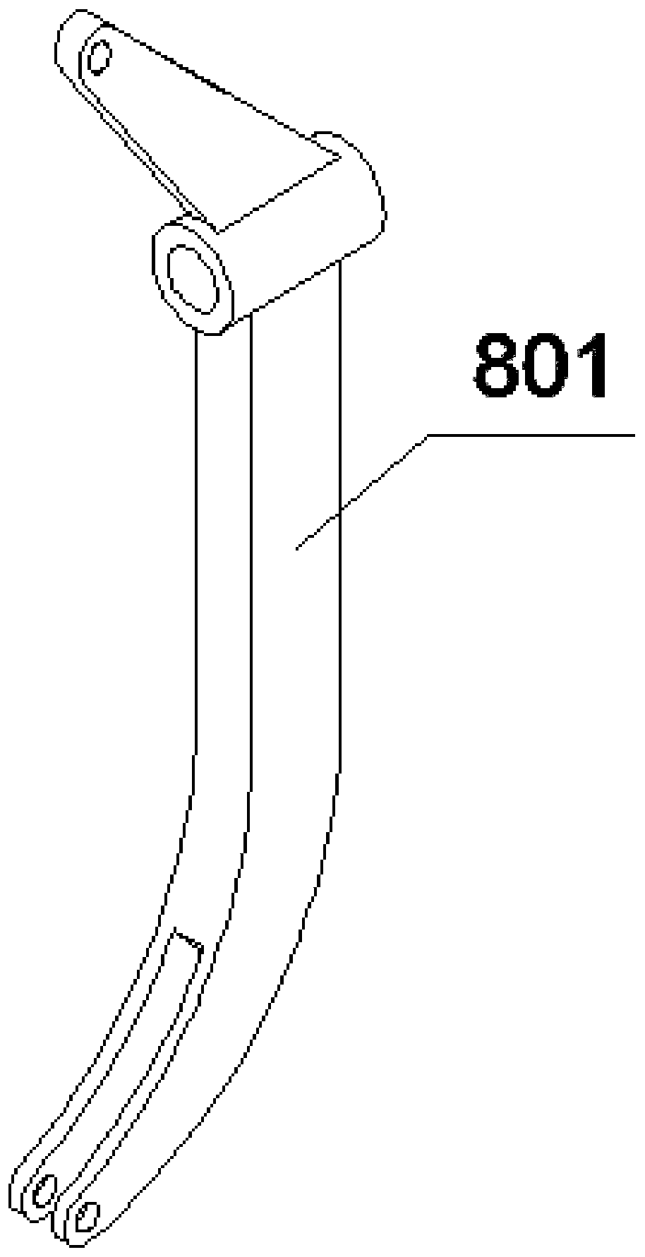
The invention provides a rotary clamping manipulator based on automatic module control. The rotary clamping manipulator based on automatic module control comprises a main swing arm, a top cover, a servo motor A, a rack belt, a servo motor B, a connecting shaft, an auxiliary device, a clamping block, a transmission cylinder, a tension screw rod, a transmission rod, an underframe, a mechanical finger, a self-adjusting finger plate, an auxiliary guide ring and a counterweight block, wherein the top of the main swing arm is provided with a T-shaped groove; the top cover is fixedly arranged in theT-shaped groove through a bolt; a through hole is formed in the end portion of the main swing arm, and hole shoulder structures are arranged in both sides of the main swing arm; and tapered roller bearings are fixedly arranged on the outer sides of hole shoulders in interference fit mode. Due to the arrangement of a rack ring, the servo motor A can be matched for axial movement, the transmission of the rack belt is matched for controlling the rotating position of the rotating arm, the rotation of the mechanical arm is completed, the structure is simple and convenient, the servo motors can be accurately controlled through a module, the rotating precision is high, the force control is uniform, and accurate placement of parts by the manipulator is facilitated.

Description

technical field [0001] The present invention relates to the technical field of mechanical equipment, and more specifically relates to a rotary clamping manipulator based on automation module control. Background technique [0002] A manipulator is an automatic operating device that can imitate certain movement functions of the human hand and arm to grab, carry objects or operate tools according to a fixed program. It is characterized in that it can be programmed to complete various expected operations. It combines the advantages of both human and robotic machines. At present, it is mainly driven by hydraulic pressure, pneumatic power and mechanical drive. [0003] Based on the application number: 201610822849.6 of the suspended pneumatic balance transfer manipulator, the present invention discloses a suspended pneumatic balance transfer manipulator, which mainly includes: a track system, a running trolley, a mechanical arm, a pneumatic clamp and an air control system; The tr...

Claims


Application Information

Patent Timeline
IPC IPC(8): B25J9/12B25J15/02B25J15/08
Inventor 郎露枫
Owner 郎露枫
Why Eureka
Try Eureka