Vibration equipment and concrete pouring vibration method for tall special-shaped column

An equipment and column technology, applied in the field of bridge construction, can solve the problems of infeasibility, high construction cost, impact on structural performance, etc., and achieve the effects of avoiding leakage and over-vibration problems, uniform color quality, and simple operation.

Active Publication Date: 2019-06-07
苏州交通工程集团有限公司
View PDF11 Cites 7 Cited by
  • Summary
  • Abstract
  • Description
  • Claims
  • Application Information

AI Technical Summary

Problems solved by technology

Attached vibration has high requirements on the rigidity and reinforcement degree of the formwork, and the construction cost is relatively high; while manual vibration at the bottom of the warehouse needs to cut off some steel bars, which has a certain impact on the structural performance, and the construction is relatively cumbersome. There is also a certain impact on safety. For special-shaped columns, it is even more unfeasible to manually enter the warehouse

Method used


Image

  • Vibration equipment and concrete pouring vibration method for tall special-shaped column
  • Vibration equipment and concrete pouring vibration method for tall special-shaped column
  • Vibration equipment and concrete pouring vibration method for tall special-shaped column

Examples


Embodiment 1

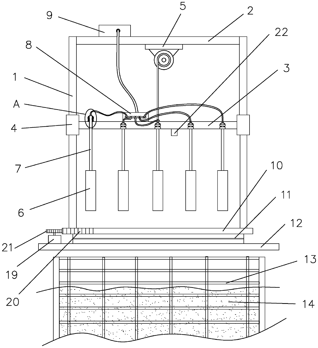
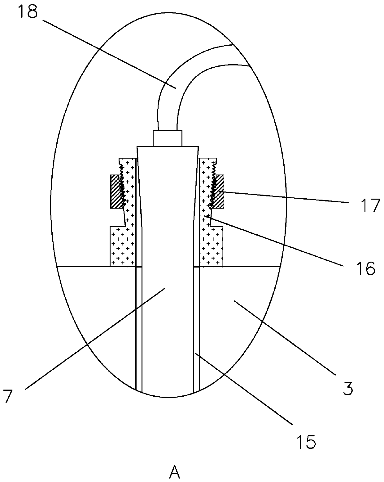
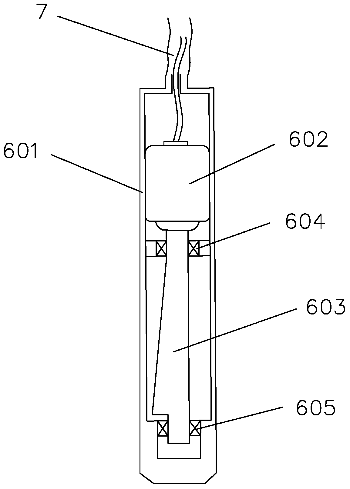
[0036] refer to figure 1 , a vibrating device, including a support frame, a driving mechanism and a vibrating system, the support frame includes at least a pair of vertically arranged support rods 1, the upper ends of each support rod 1 are connected and fixed by connecting beams 2, and the inner side of the support frame A suspension 3 is provided, and the edge of the suspension 3 is provided with a sleeve 4 slidingly sleeved on the support rod 1, so that the suspension 3 can move up and down, and the connecting beam 2 is installed and fixed for pulling the suspension 3 up and down. The lifting motor 5 of the lifting motor, the lifting motor 5 traction rope is connected and fixed with the suspension 3, and the vibrating system includes a plurality of vibrating rods 6, a main controller 9 for controlling the vibrating rods 6, and a plurality of vibrating rods 6 The tap 8 connected to the main controller 9, the vibrating rod 6 is suspended below the suspension 3, the upper end ...

Embodiment 2

[0043] Since the shape and area of ​​the cross-section of the concrete with special-shaped columns at different heights are different, this vibrating method adopts the method of vibrating while injecting concrete into the reinforced grid frame, and needs to follow the As the concrete rises, the height of the vibrating rod is increased, so the vibrating method is designed as follows.

[0044] refer to Figure 6 , a method for vibrating tall and large special-shaped column concrete pouring, comprising the following steps:

[0045] S1. According to the height and shape of the column concrete, mark the height along its height direction;

[0046] S1. Use a crane to lift the vibrating equipment and erect it on the top of the reinforced grid, and determine the number and position of the vibrating rods installed on the suspension according to the cross-sectional area and shape of the vibrating area at the current height of the column ( That is, which installation holes should instal...


PUM


Abstract

The invention relates to vibration equipment and a concrete pouring vibration method for a tall special-shaped column. The vibration equipment and the vibration method thereof can replace manual construction, a vibration rod is lifted with the rise of concrete height, so that the surface color of concrete is uniform and air bubbles are less, the structural problems caused by cutting steel bars andthe problems of missed-vibration and over-vibration caused by manual operation errors are avoided, and the vibration rod is suitable for pouring concrete with different shapes of special-shaped columns. The equipment and the vibration method thereof are not only low in investment and simple in operation, but also high in efficiency and safety.

Description

technical field [0001] The invention relates to the field of bridge construction, and more specifically relates to a vibrating equipment and a vibrating method for pouring concrete with tall and special-shaped columns. Background technique [0002] Usually, there will be a lot of air bubbles and voids in the concrete after pouring. If it is hardened directly without treatment during construction, it will affect the strength of the concrete, resulting in a hornet's honeycomb structure or cracking in the later stage. [0003] In the existing methods, generally, a vibrator is attached to the formwork for vibrating or a construction method of vibrating manually into a warehouse is adopted. Attached vibration has high requirements on the rigidity and reinforcement degree of the formwork, and the construction cost is relatively high; while manual vibration at the bottom of the warehouse needs to cut off some steel bars, which has a certain impact on the structural performance, and...

Claims


Application Information

Patent Timeline
Patent Type & Authority Applications(China)
IPC IPC(8): E01D21/00
Inventor 赵云斌焦宗琴王国亭王伟伟
Owner 苏州交通工程集团有限公司
Why Eureka
Try Eureka