Counterweight device for heavy equipment

A technology of counterweight device and heavy equipment, which is applied in the direction of earth mover/shovel, construction, etc., can solve the problems of difficulty in guaranteeing the gap between the cover body and the counterweight, damage to the mating contact, damage to electrical components, etc., to eliminate Damage to electrical components in the engine compartment, eliminate paint blistering, smooth and soft opening

Pending Publication Date: 2019-06-07
山重建机有限公司
View PDF0 Cites 0 Cited by
  • Summary
  • Abstract
  • Description
  • Claims
  • Application Information

AI Technical Summary

Problems solved by technology

[0004] The following problems exist: 1. The engine cover and the counterweight are installed independently, the assembly process is poor, the gap between the cover and the counterweight is difficult to guarantee, and the vibration frequency of the counterweight and the engine cover is different during the operation of the equipment, resulting in premature damage to the mating contact and locks. Fracture; 2. One end of the gas spring is arranged on the door frame, and the other end is arranged on the engine hood. The force arm is small and the nominal force is large, which causes a large reaction force on the door frame and the engine hood, deforming or partially breaking the door frame and the engine hood. ;3. There is no water guide groove at the contact between the engine cover and the counterweight, rainwater will flow into the engine compartment, damage electrical components, and local water accumulation will cause the paint surface of the parts to peel

Method used


Image

  • Counterweight device for heavy equipment
  • Counterweight device for heavy equipment
  • Counterweight device for heavy equipment

Examples


Embodiment Construction

[0022] The present invention will be further described below in conjunction with specific examples. It should be understood that these examples are only used to illustrate the present invention and are not intended to limit the scope of the present invention. In addition, it should be understood that after reading the teachings of the present invention, those skilled in the art can make various changes or modifications to the present invention, and these equivalent forms also fall within the scope defined by the appended claims of the application.

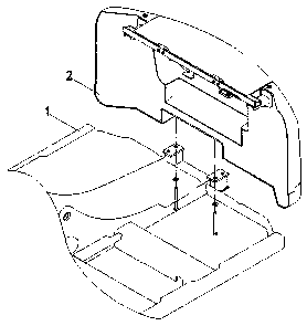
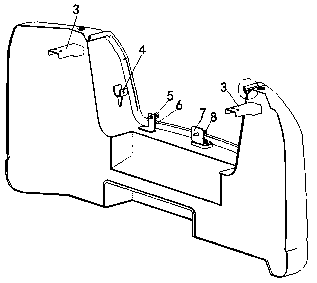
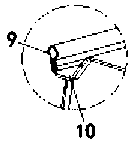
[0023] see Figures 1 to 6 It is an axonometric view for describing the assembly of the present invention, a schematic structural view of the counterweight body 14, figure 2 Partially enlarged schematic diagram, structural schematic diagram of engine cover 15, axonometric diagram for description, and axonometric diagram for description of operation, which include gas spring mounting seat A4, crossbeam 18 mounting seat 3, positioni...


PUM


Abstract

The invention discloses a counterweight device for heavy equipment. The counterweight device is of concave structure; a water guiding groove is formed at the contact position of a counterweight body and an engine cover; a sealing strip is arranged inside the water guiding groove; a beam mounting seat for mounting a beam is arranged on the inner side wall of the counterweight body; a gas spring mounting seat A is arranged at the inner side wall of the counterweight body and is connected with a gas spring joint; a mounting seat is arranged on a frame; the counterweight body is fixed onto the mounting seat; and the two ends of the beam are correspondingly fixed onto the mounting seat arranged on the frame. According to the counterweight device, the general assembly of the engine hood and thecounterweight body is achieved; the abrasion, breakage and breakdown of lockset are eliminated; the deformation, breakage and breakdown of a door frame caused by the reaction force of a gas spring areeliminated; the sealing property is good; the rainwater and mud are prone to be removed; and the functions of bubbles formed at paint surfaces and the damage of electrical components in an engine compartment are eliminated.

Description

technical field [0001] The invention relates to the technical field of engineering machinery, in particular to a counterweight device for heavy equipment. Background technique [0002] Construction machinery is an important part of the equipment industry. Generally speaking, the mechanical equipment necessary for comprehensive mechanized construction projects required for earthwork construction projects, road surface construction and maintenance, mobile lifting and unloading operations, and various construction projects is called As construction machinery, it is mainly used in national defense construction projects, transportation construction, energy industry construction and production, mining and other raw material industry construction and production, agriculture, forestry and water conservancy construction, industrial and civil construction, urban construction, environmental protection and other fields. [0003] Generally speaking, heavy equipment such as small and medi...

Claims


Application Information

Patent Timeline
Patent Type & Authority Applications(China)
IPC IPC(8): E02F9/08E02F9/18
Inventor 李瑞光魏敬成李晖付信玉尹彬朱东烈刘永祥李杰
Owner 山重建机有限公司
Why Eureka
Try Eureka