

Full swing structural system containing swing columns and swing walls and construction method of full swing structural system
A swinging wall and swinging column technology, applied in the direction of walls, building components, building structures, etc., can solve the problems of insufficient lateral rigidity, inconvenient construction, insufficient wind resistance and small earthquake resistance, etc. Forced clear effect
- Summary
- Abstract
- Description
- Claims
- Application Information
AI Technical Summary
Problems solved by technology
Method used
Image

Examples
Embodiment 1
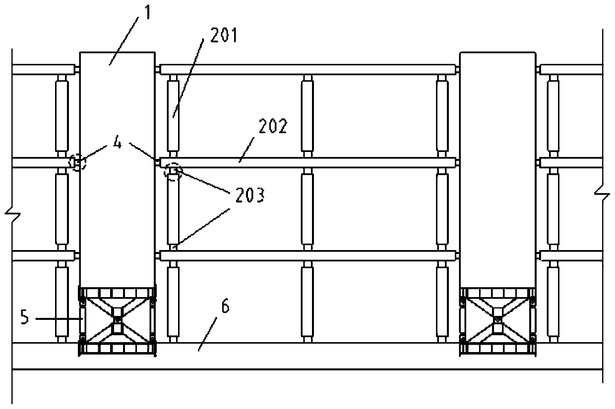
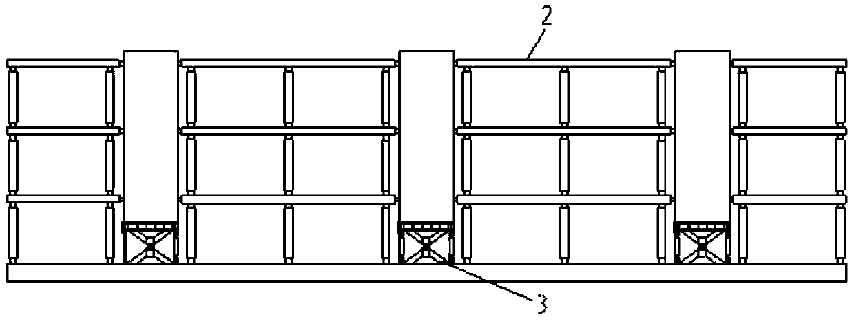
[0041] see figure 1 and figure 2 , the present embodiment 1 discloses a full swing structure system including a swing column and a swing wall, including a swing wall 1 and a frame structure 2 arranged above the foundation beam 6 .
[0042] Each of the swing walls 1 is arranged between two adjacent frame structures 2 . The bottom of the swing wall 1 is hinged to the upper surface of the foundation beam 6 through the X-shaped support 3 at the bottom of the wall.
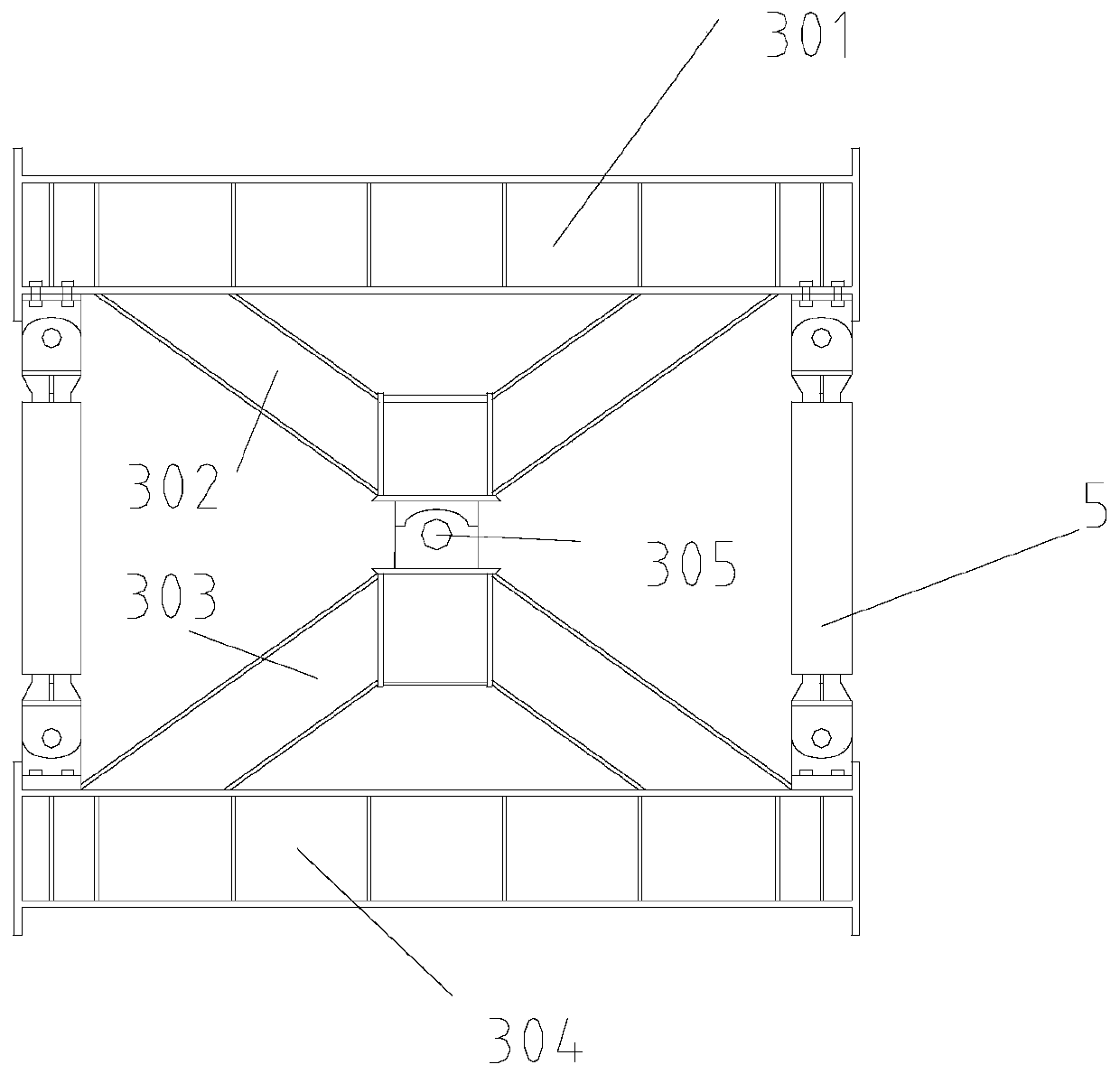
[0043] see image 3 , the X-shaped support 3 at the bottom of the wall includes a top outsourcing steel plate 301 , an X-shaped part and a bottom outsourcing steel plate 304 . The top cladding steel plate 301 is fixed on the bottom surface of the swing wall 1 . The bottom outer cladding steel plate 304 is embedded and fixed on the upper surface of the foundation beam 6 . The X-shaped portion includes an upper V-shaped plate 302 and a lower V-shaped plate 303 . The open end of the upper V-shaped plate 302 faces u...
Embodiment 2
[0049] This embodiment discloses a construction method for the structural system described in Embodiment 1, comprising the following steps:
[0050] 1) Pouring foundation beam 6.
[0051] 2) Install the X-shaped support 3 and the anti-buckling support 5 at the bottom of the wall.
[0052] 3) Install the bottom swing column 202 .
[0053] 4) Set up support and formwork, and pour the swing wall 1.
[0054] 5) Install the frame beam 201 and the recoverable column foot 203 .
[0055] 6) Install the energy dissipation damper 4, and connect the swing wall 1 and the frame beam 201.
[0056] 7) Install the swing column 202 in the middle layer.
[0057] 8) Repeat steps 5-7 until all components are installed.
PUM
 Abstract
Description
Claims
Application Information