Temperature detecting circuit for IGBT module

A temperature detection circuit and circuit technology, which is applied to thermometers, thermometers, and electrical devices that use directly heat-sensitive electric/magnetic components, can solve the problem of inaccurate, true and effective measurement of module junction temperature, and the error is difficult to meet high requirements. Accurate temperature measurement requirements, measurement module junction temperature and other issues, to achieve efficient and practical process design, easy detection, and easy mass production

Pending Publication Date: 2019-06-07
ACREL +1
View PDF0 Cites 9 Cited by
  • Summary
  • Abstract
  • Description
  • Claims
  • Application Information

AI Technical Summary

Problems solved by technology

However, due to the characteristics of NTC sensors, the resistance value will change with different temperatures, and the range of change can reach more than a thousand times. The AD sampling digits of common single-chip microcomputers are usually ten digits, plus the system noise during the acquisition process, the measurement error It is difficult to meet the requirements of high-precision temperature measurement in the whole temperature range
[0005] 2. The comparator comparison method, the circuit is simple, it can only be used as an over-temperature protection judgment for setting the maximum temperature of the IGBT, and the junction temperature of the module cannot be measured linearly
[0006] 3. The indirect measurement method is not to directly measure the actual temperature of the chip, but to measure the temperature of other reference points in the system, usually to detect the temperature of the substrate or radiator of the IGBT module, which cannot accurately and effectively measure the junction temperature of the module
[0007] Moreover, these methods do not have isolation detection, and the linearity and accuracy are not high.

Method used


Image

  • Temperature detecting circuit for IGBT module
  • Temperature detecting circuit for IGBT module
  • Temperature detecting circuit for IGBT module

Examples


specific Embodiment

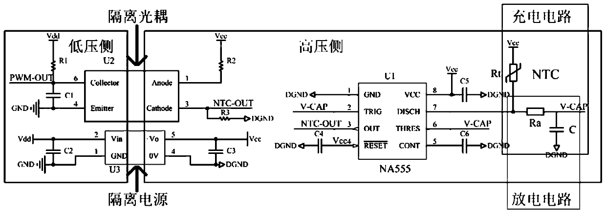
[0056] 1. First, the capacitor voltage is 0, the internal discharge tube of U1 is disconnected, and the power supply Vcc charges C through Rt and Ra. When the voltage of C reaches 1 / 3Vcc, pin 3 outputs a high level until the voltage across the capacitor C reaches 2 When / 3Vcc, the internal discharge tube of U1 is closed, the capacitor C is discharged through the resistor Ra, and pin 3 outputs a low level. When the voltage across the discharged capacitor C reaches 1 / 3Vcc, the internal discharge tube of U1 is disconnected. In this way, the capacitor C is charged and discharged repeatedly, and the pin 3 of U1 outputs the corresponding high and low levels, thereby converting the change of the resistance value of the thermistor Rt of the IGBT module into a change of the pulse width.

[0057] 2. The pulse output by U1 is isolated by the high-speed optocoupler U2 and then sent to the FPGA for calculation. The pulse width is read out, and the corresponding IGBT module junction temperat...


PUM


Abstract

The invention relates to a temperature detecting circuit for an IGBT module. The temperature detecting circuit for the IGBT module comprise a thermistor Rt, a chip U1 for converting an analog quantityinto an pulse quantity, and an FPGA, wherein the thermistor Rt is installed inside the IGBT module; the chip U1 for converting the analog quantity into the pulse quantity is connected with the thermistor Rt and used for converting an analog quantity of resistance change of the thermistor Rt into a digital quantity of a pulse width change; and the FPGA is connected with the chip U1 for convertingthe analog quantity into the pulse quantity, and the FPGA is used for detecting a pulse width or a duty ratio, calculating an NTC resistance value, and reading an corresponding IGBT module junction temperature through a look-up table method. Compared with the prior art, the temperature detecting circuit for the IGBT module has the advantages of having good linearity, high precision, and safety isolation.

Description

technical field [0001] The invention relates to a temperature detection circuit, in particular to a temperature detection circuit for an IGBT module. Background technique [0002] With the rapid development of modern industry, power electronics technology has also been advancing by leaps and bounds. Power semiconductors are the most important devices, and power modules are widely used in the field of power electronics conversion, especially in new energy vehicles, energy storage, and frequency conversion. Power modules play an extremely important role in popular industries such as power converters, active filters, and SVG. In the actual application process, the high IGBT junction temperature caused by uneven heat dissipation of the substrate and internal overcurrent is one of the main reasons for module failure. An important factor restricting the application of semiconductors is also their maximum junction temperature Tvj, so whether it is Whether the application developer...

Claims


Application Information

Patent Timeline
Patent Type & Authority Applications(China)
IPC IPC(8): G01K7/24
Inventor 洪文瓞赵军苏振宇赵立坤季晓春胡勇祥董建锋李烽
Owner ACREL
Why Eureka
Try Eureka