Eureka AIR delivers breakthrough ideas for toughest innovation challenges, trusted by R&D personnel around the world.

Vibration power generation device of automobile

A technology for vibration power generation and automobiles, applied in the field of vehicles, can solve the problems of shortening the service life of the battery, damage to the battery, and small electric energy, and achieve the effect of prolonging the service life and avoiding damage.

Active Publication Date: 2019-06-07
CHONGQING VOCATIONAL COLLEGE OF TRANSPORTATION
View PDF7 Cites 2 Cited by
  • Summary
  • Abstract
  • Description
  • Claims
  • Application Information

AI Technical Summary

Problems solved by technology

[0004] At present, there are more and more researches on the energy conversion of the mechanical energy generated by the vibration during the driving process of the car. The main direction is to install a power generation device on the shock absorber of the car, and use the power generation device to convert the mechanical energy generated during the vibration process. Convert it into electrical energy, and rectify the electrical energy to charge the battery. This energy conversion method has the following problems in the actual use process: 1. Because the vibration amplitude during the driving process of the car will vary from time to time , when the vibration amplitude of the car is too small, the mechanical energy generated by the car vibration is also small, and the electrical energy converted from the mechanical energy is also small, because there are more electrical components in the charging system for charging the battery, such as diodes, IGBTs, etc., and During the use of the diode, the voltage applied to both ends of the diode needs to be greater than a certain value before it can be turned on, that is, the voltage can be turned on. When the car vibration is small and the converted electric energy is small, the electric energy will not be enough to make the charging system conduction to charge the battery. charging, which in turn will lead to the waste of this part of the energy
2. When the vibration amplitude of the car is too large during driving, the electrical energy converted from the mechanical energy of the vibration is also relatively large, and when the relatively large electric energy is charged to the battery through the charging system, it is easy to dissipate the energy in the charging system. Breakdown of electrical components will cause damage to the entire charging system. In order to avoid breakdown of electrical components, only high-power electrical components are needed, which will greatly increase the operating cost of the entire charging system.
3. With the development of the national economy, the construction of roads in various places is becoming more and more perfect, and the smoothness of the roads is getting better and better. Therefore, when cars are driving on these roads, most of the time there is a small vibration. Therefore, the use of the traditional charging system will cause most of the electric energy converted from the mechanical energy of the car vibration to be unable to be used to charge the battery, so that most of the mechanical energy in the car vibration process will not be effectively used, resulting in a waste of energy
4. Since the vibration amplitude of the car during driving is sometimes large and sometimes small, the electric energy converted from mechanical energy will also have a large and sometimes small current when charging the battery. Long-term charging in this way will cause damage to the battery and shorten the life of the battery. service life

Method used


Image

  • Vibration power generation device of automobile
  • Vibration power generation device of automobile
  • Vibration power generation device of automobile

Examples


Embodiment Construction

[0038] The present invention will be further described in detail below in conjunction with the accompanying drawings.

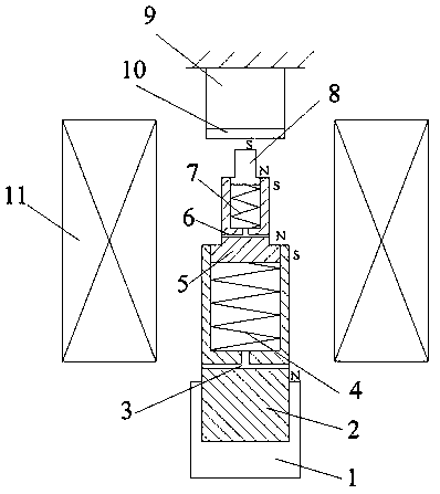
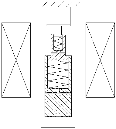
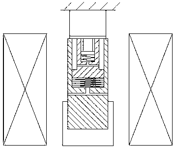
[0039] A vibration power generation device for a car, as attached figure 1 As shown, it includes a hollow induction coil mechanism 11 and a permanent magnet telescopic mechanism fixedly connected with the shock absorber 1 of the automobile. The permanent magnet telescopic mechanism can move back and forth in the direction of the central axis of the induction coil mechanism 11. Arranged along the direction of the central axis of the induction coil mechanism 11, a plurality of permanent magnets are arranged on the permanent magnet expansion mechanism, and the plurality of permanent magnets can move away from or approach each other when the permanent magnet expansion mechanism stretches, thereby generating different magnetic fields. The fixed end is used to be connected with the shock absorber 1 of the automobile, and the limit stopper 9 that can be contacted w...


PUM


Abstract

The invention discloses a vibration power generation device of an automobile. The device comprises a hollow induction coil mechanism and a permanent-magnet telescoping mechanism, wherein the permanent-magnet telescoping mechanism can move to and fro along a central axis direction of the induction coil mechanism; the telescoping direction of the permanent-magnet telescoping mechanism is arranged along the central axis direction of the induction coil mechanism; a plurality of permanent magnets are arranged on the permanent-magnet telescoping mechanism; during the telescoping of the permanent-magnet telescoping mechanism, the permanent magnets can be far away from each other or close to each other to generate magnetic fields with different sizes; a limiting stop which can be in contact with atelescoping end of the permanent-magnet telescoping mechanism is arranged right above the telescoping end of the permanent-magnet telescoping mechanism; and the limiting stop is fixedly connected with a frame of the automobile. According to the device, stable induction current can be output all the time to charge storage batteries, so that the condition that the storage batteries cannot be charged as the vibration amplitude is too small is avoided, and the damages caused to charging systems as the induction current output is too large when the vibration amplitude is too large are avoided.

Description

technical field [0001] The invention relates to the technical field of vehicles, in particular to a vibration power generation device for an automobile. Background technique [0002] With the development of the world economy, the consumption of energy has also increased greatly. As far as the current situation is concerned, due to the serious imbalance between supply and demand of oil-based energy, the price has skyrocketed, affecting and affecting the economic development of all parts of the world, and bringing great risks to the development of the world economy. With the improvement of people's living standards, the number of automobiles is increasing, and the proportion of automobile energy consumption in the total energy consumption is getting higher and higher, and the issue of automobile energy saving has also attracted more and more attention. [0003] The suspension system refers to a connecting structural system between the body, frame and wheels, and this structur...

Claims


Application Information

Patent Timeline
Patent Type & Authority Applications(China)
IPC IPC(8): H02J7/32H02K35/02B60K25/10
Inventor 周佰和周天娇周天明刘雅丹
Owner CHONGQING VOCATIONAL COLLEGE OF TRANSPORTATION
Why Eureka
Eureka Blog
Learn More