Dynamic control method for state machine of relay protection equipment of intelligent substation

An intelligent substation and relay protection technology, applied in electrical components, circuit devices, information technology support systems, etc., can solve the problems of secondary equipment status that does not support online real-time identification, the corresponding relationship cannot be clearly defined, and the classification granularity of the pressure plate is coarse. , to achieve the effect of preventing large-scale power outages in the power grid, considerable economic and social benefits, and preventing damage to primary power equipment

Active Publication Date: 2019-06-07
CHINA SOUTHERN POWER GRID COMPANY +1
View PDF7 Cites 3 Cited by
  • Summary
  • Abstract
  • Description
  • Claims
  • Application Information

AI Technical Summary

Problems solved by technology

[0005] The classification granularity of the pressure plate is coarse, and the state judgment is not sensitive or accurate;
[0006] The corresponding relationship between the external associated interval pressure plate and the operating branch cannot be clearly defined. In some operating modes, the status of the secondary equipment does not support online real-time identification, and requires manual identification and confirmation by operation and maintenance personnel

Method used


Image

  • Dynamic control method for state machine of relay protection equipment of intelligent substation
  • Dynamic control method for state machine of relay protection equipment of intelligent substation
  • Dynamic control method for state machine of relay protection equipment of intelligent substation

Examples


Embodiment 1

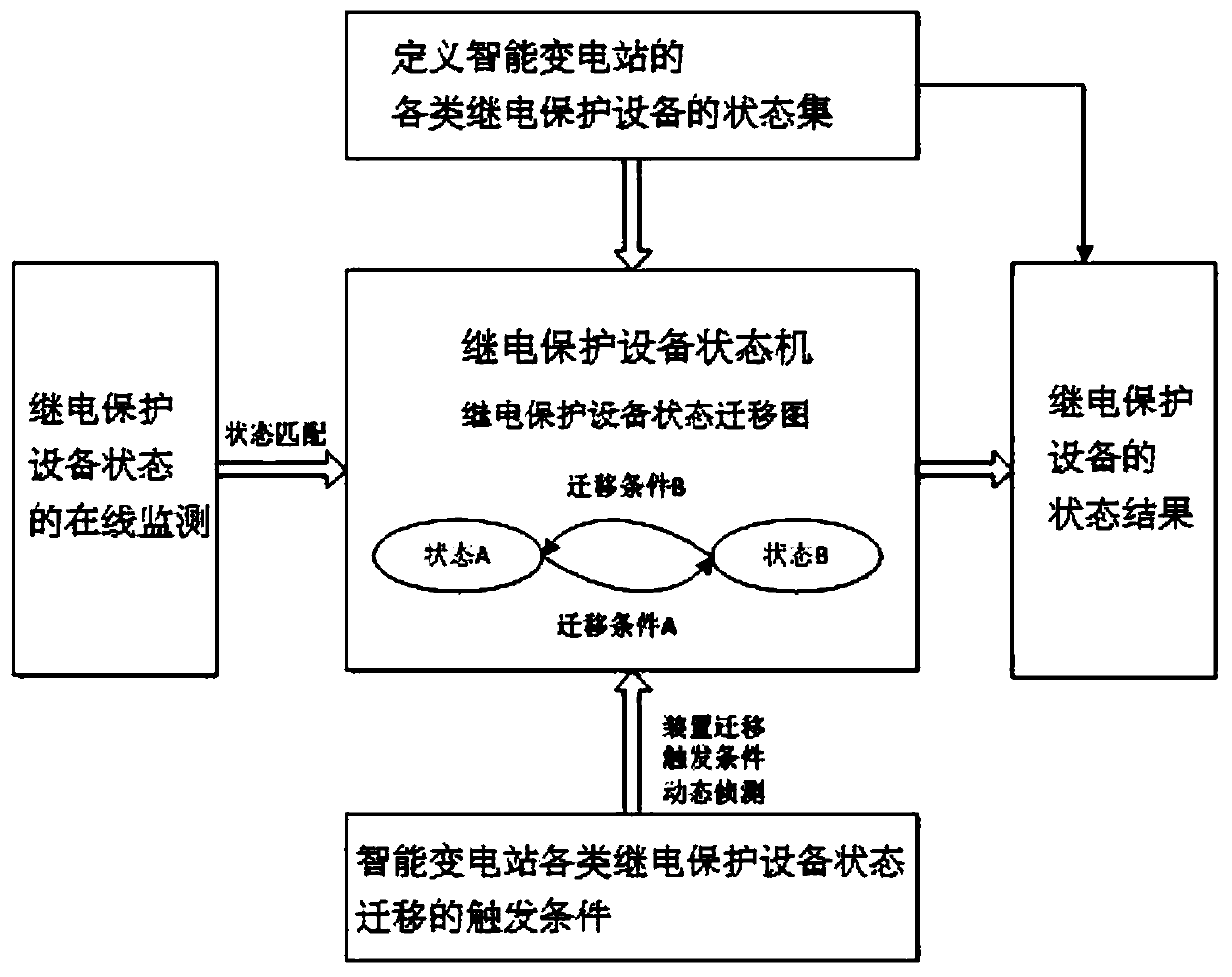
[0046] Such as figure 1 As shown, a kind of intelligent substation relay protection equipment state machine dynamic control method of the present invention is carried out according to the following steps:

[0047] Step S101, through the intelligent substation integrated automation system, collect the position information and real-time voltage and current values ​​of the primary equipment switch, isolation switch, and grounding switch, and combine the primary topology to calculate the state of the primary interval, which is defined as running, hot standby, and cold standby , Maintenance four states;

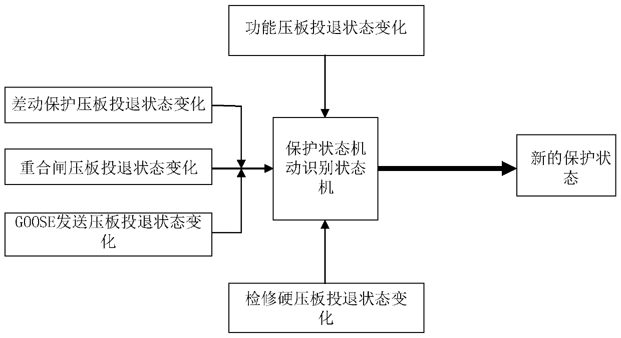
[0048] Step S102, according to the needs of state identification of various relay protection devices in the smart substation, extract, classify and integrate all information of the various relay protection devices in the smart substation, and form two data sets, including normal operation status information and functional pressure plate information of the relay protection devices....

Embodiment 2

[0058] Step S201, through the intelligent substation integrated automation system, collect the position information and real-time voltage and current values ​​of the primary equipment switch, isolation switch, and grounding switch, and combine the primary topology to calculate the state of the primary interval, which is defined as running, hot standby, and cold standby , Maintenance four states;

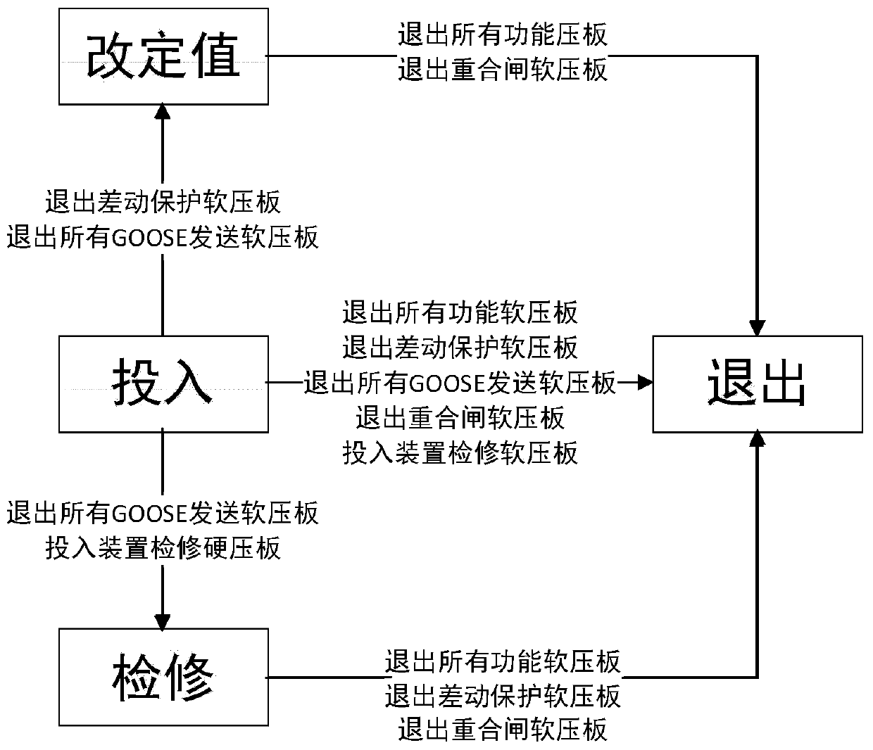
[0059] Step S202, according to the needs of status identification of various relay protection devices in the smart substation, extract, classify and integrate all the information of the various relay protection devices in the smart substation, and form two sets of information, including normal operation status information and functional pressure plate information of the relay protection devices. Among them, the normal operation status of the relay protection device is composed of three types of information, which are ① the device is running; ② the device has no alarm information; ③ th...

Embodiment 3

[0070] Step S301, through the intelligent substation integrated automation system, collect the position information and real-time voltage and current values ​​of the primary equipment switch, isolation switch, and grounding switch, and combine the primary topology to calculate the state of the primary interval, which is defined as running, hot standby, and cold standby , Maintenance four states;

[0071] Step S302, according to the needs of status identification of various relay protection devices in the smart substation, extract, classify and integrate all information of the various relay protection devices in the smart substation, and form two data sets, including normal operation status information and functional pressure plate information of the relay protection devices. Among them, the normal operation status of the relay protection device is composed of three types of information, which are ① the device is running; ② the device has no alarm information; ③ the device has n...


PUM


Abstract

The invention discloses a dynamic control method for a state machine of relay protection equipment of an intelligent substation. The method comprises the steps of defining a state set of each type ofrelay protection equipment of the intelligent substation; defining a state transition diagram control direction of the relay protection equipment to form a state transition diagram of each type of relay protection equipment; defining a state transition trigger condition of each type of relay protection equipment of the intelligent substation; dynamically matching a current state of each relay protection equipment of the intelligent substation; completing dynamic detection of the state transition trigger condition of the relay protection equipment; and outputting a state result of the relay protection equipment, and achieving state identification of the relay protection equipment of the intelligent substation. According to the method provided by the invention, the state of the relay protection equipment of the intelligent substation can be dynamically identified, and a foundation is laid for achieving non-correspondence monitoring and maintenance and safety verification application of running states of primary and secondary equipment of the intelligent substation.

Description

technical field [0001] The invention belongs to the technical field of electric power system relay protection, and in particular relates to a method for dynamic control of a state machine of relay protection equipment in an intelligent substation. Background technique [0002] In recent years, there have been a number of accidents in China caused by incorrect operation equipment protection functions, such as the loss of voltage in the 330kV Qingshuihe Substation of Ningxia Power Grid in 2013, the loss of voltage in the 330kV Yongdeng Substation of Gansu Power Grid in 2014, and the loss of voltage in the 330kV Yongdeng Substation of Gansu Power Grid in 2018. Accidents such as loss of voltage in the 220kV Penglai substation in Zhoushan, Zhejiang, were all caused by the incorrect input or withdrawal of the relay protection pressure plate (the state of the secondary equipment of the relay protection does not correspond to the state of the primary equipment), resulting in the lock...

Claims


Application Information

Patent Timeline
Patent Type & Authority Applications(China)
IPC IPC(8): H02J13/00
CPCY04S10/16
Inventor 丁晓兵张弛徐小俊纪陵黄佳胤兰金波余江周红阳李靖霞徐鹏彭业刘千宽郑茂然高宏慧
Owner CHINA SOUTHERN POWER GRID COMPANY
Why Eureka
Try Eureka