

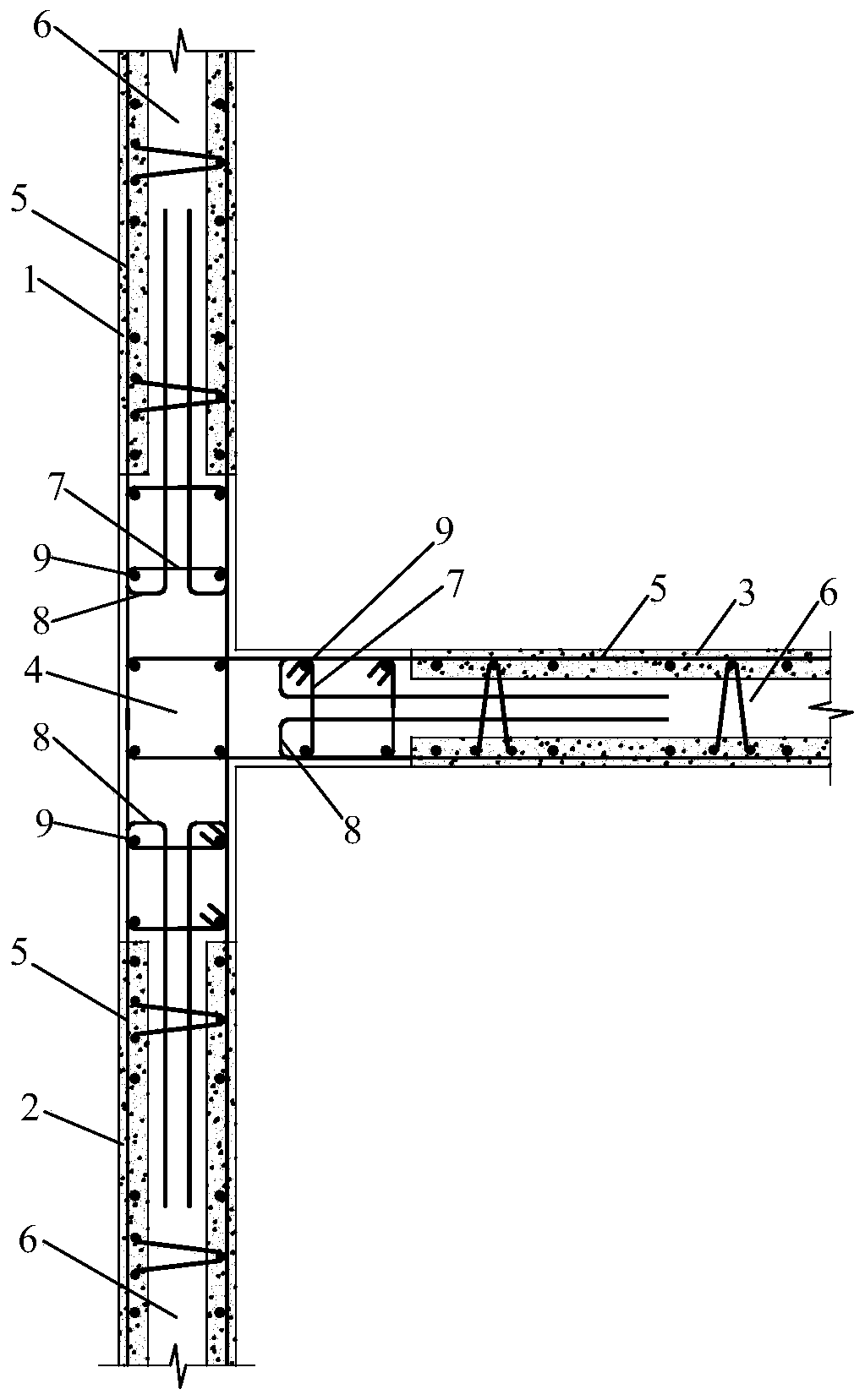
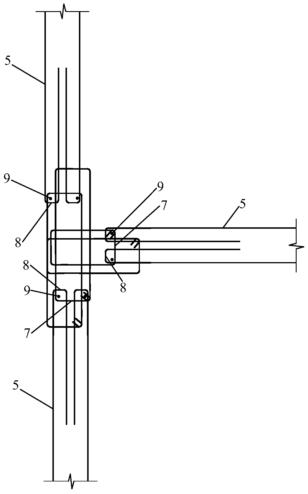
Connection structure of T-shaped superimposed shear wall edge member
A technology for superimposing shear walls and edge components, which is applied to building components, building structures, walls, etc., can solve the problems of complex construction, too many binding steel bars for edge components, and easy formation of joints, so as to improve the coordinated deformation ability, Prevent local shear damage and ensure the effect of overall force bearing
- Summary
- Abstract
- Description
- Claims
- Application Information
AI Technical Summary
Problems solved by technology
Method used
Image

Examples
Embodiment Construction
[0016] The following will clearly and completely describe the technical solutions in the embodiments of the present invention with reference to the accompanying drawings in the embodiments of the present invention. Obviously, the described embodiments are only some, not all, embodiments of the present invention. Based on the embodiments of the present invention, all other embodiments obtained by persons of ordinary skill in the art without creative efforts fall within the protection scope of the present invention.
[0017] It should be noted that, in the case of no conflict, the embodiments of the present invention and the features in the embodiments can be combined with each other.
[0018] The present invention will be further described below in conjunction with the accompanying drawings and specific embodiments, but not as a limitation of the present invention.
[0019] Such as figure 1 , figure 2 As shown, the connection structure of the T-shaped laminated shear wall ed...
PUM
 Abstract
Description
Claims
Application Information