Vertically-supported micro-piezoelectric pump

A piezoelectric pump and miniature technology, which is applied in the direction of pumps, pumps with flexible working elements, and liquid variable capacity machinery, etc., can solve the problems of output capacity limitation and piezoelectric pump output capacity reduction, etc., to improve performance, improve The effect of output flow and output pressure, volume reduction and peripheral size

Pending Publication Date: 2019-06-11
常州威图流体科技有限公司
View PDF2 Cites 4 Cited by
  • Summary
  • Abstract
  • Description
  • Claims
  • Application Information

AI Technical Summary

Problems solved by technology

However, the more miniaturization and low voltage are required, the more the output capacity (output pressure and output flow) of the piezoelectric pump will be reduced, and the output capacity has a limit that cannot be exceeded.

Method used


Image

  • Vertically-supported micro-piezoelectric pump
  • Vertically-supported micro-piezoelectric pump
  • Vertically-supported micro-piezoelectric pump

Examples


Embodiment 1

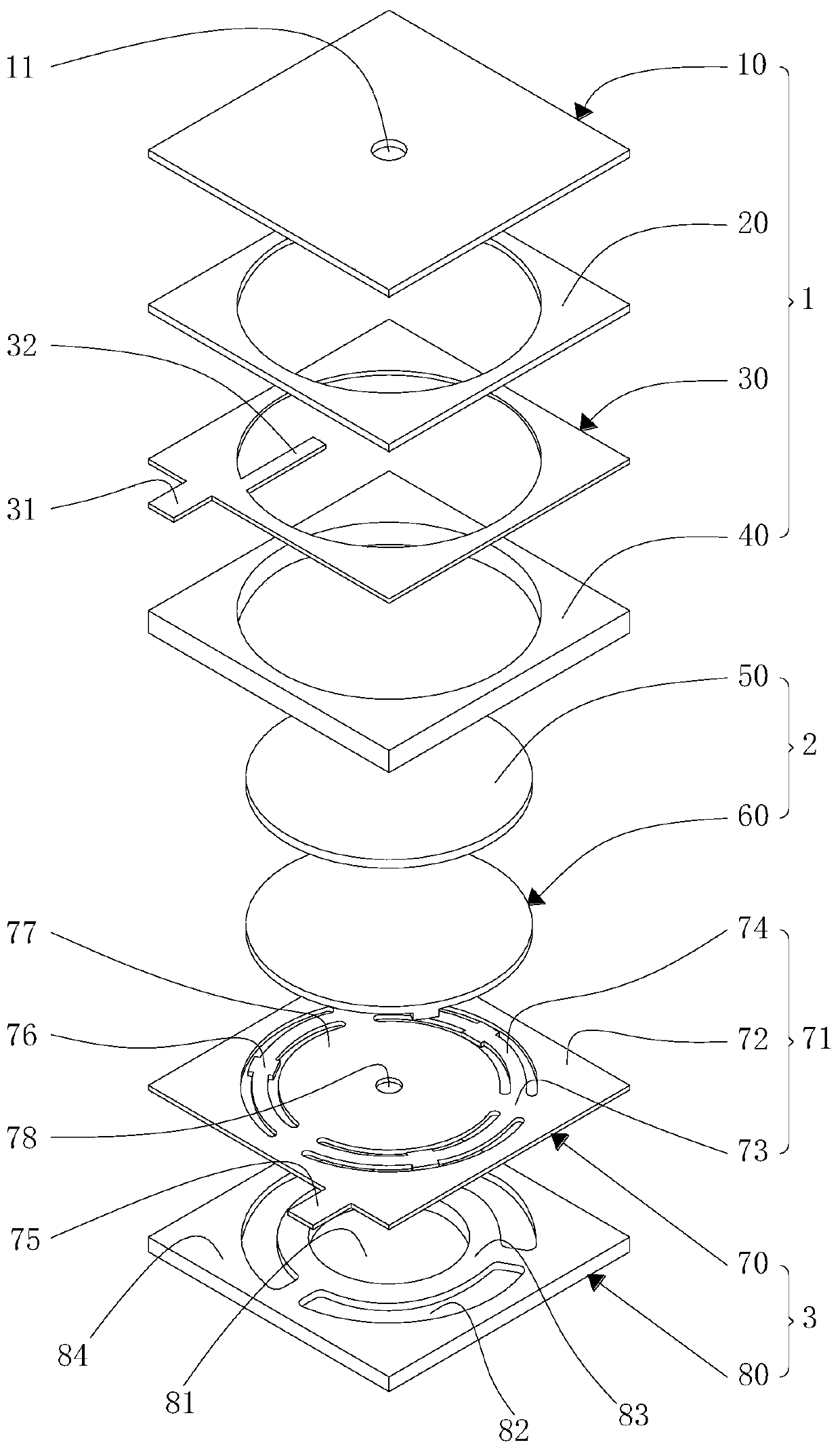
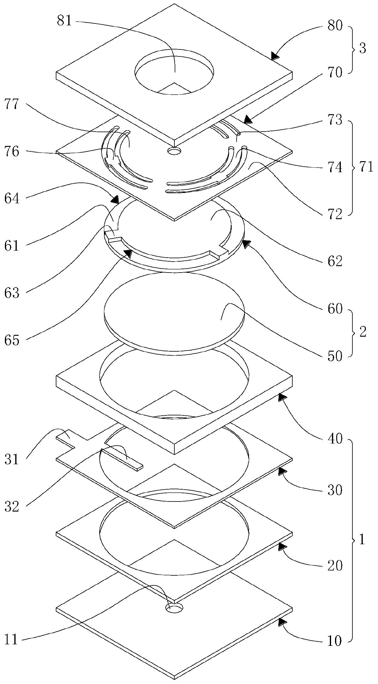
[0046] Such as Figure 1-4As shown, the vertically supported micro piezoelectric pump of this embodiment includes a pump body 1, an actuator 2 and a support structure 3, wherein the pump body 1 and the support structure 3 are sealed and connected to form a pump cavity 4, and the shape of the actuator 2 Smaller than the pump chamber 4, the actuator 2 is arranged inside the pump chamber 4 and connected to the support structure 3, and the pump body 1 and the support structure 3 are respectively provided with the pump chamber 4 in the area corresponding to the upper and lower sides of the actuator 2. air vent.

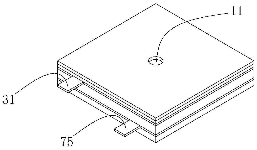
[0047] Wherein, the pump body 1 includes a cover plate 10, a first separator 20, an electrode plate 30 and a second separator 40 which are sequentially sealed and connected from top to bottom. The cover plate 10 is provided with an air hole 11 communicating with the pump cavity 4, The first separator 20, the electrode plate 30 and the second separator 40 are all provided ...

Embodiment 2

[0055] Such as Figure 10-13 As shown, the piezoelectric pump of this embodiment is basically the same as the first embodiment, the difference is that a sealed cavity 5 is provided between the substrate body 64 and the protrusion 65, and the sealed cavity 5 is approached by the substrate body 64 and the protrusion 65. The inner concave surface on one side of the substrate body 64 is sealed, such as Figure 10 and Figure 11 As shown, or the inner concave surface of the substrate body 64 near the side of the protrusion 65 is sealed with the protrusion 65, such as Figure 12 and Figure 13 As shown, the sealed cavity 5 is filled with liquid or gaseous medium, which can amplify the vibration amplitude when the vibrating substrate 60 bends and vibrates.

Embodiment 3

[0057] Such as Figure 14-15 As shown, the piezoelectric pump of this embodiment is basically the same as that of Embodiment 1, the difference is that, in order to further increase the output flow and output pressure, the side of the circular surface 62 away from the substrate body 64 is provided with a concave and extends to the escape portion 61 The depth of the flow channel is less than or equal to the depth of the avoidance part 61. Further, the shape of the flow channel includes but is not limited to the annular flow channel 66 and the circular radial flow channel 67, which is not specifically limited here. .


PUM


Abstract

The invention belongs to the technical field of fluid conveying, and relates to a vertically-supported micro-piezoelectric pump. The vertically-supported micro-piezoelectric pump comprises a pump body, a supporting structure, an actuator and one or more air holes, wherein a pump cavity is formed by the supporting structure and the pump body, the actuator is arranged in the pump cavity and connected with the supporting structure, and the air holes communicating with the pump cavity are formed in the pump body and the supporting structure; the actuator comprises a vibration base plate and one ormore piezoelectric elements arranged on the vibration base plate, and a plurality of avoidance parts are arranged on the side, close to the supporting structure, of the vibration base plate; and thesupporting structure includes a bottom plate, a flexible plate is arranged on the side, close to the vibration base plate, of the bottom plate, beam parts corresponding to the positions of the avoidance parts are arranged on the flexible plate, and avoidance grooves corresponding to the positions of the beam parts are formed in the bottom plate. According to the vertically-supported micro-piezoelectric pump, the volume and the peripheral size of the micro-piezoelectric pump can be reduced under the premises that the output capacity (output pressure and output flow) is not changed or increasedand the driving voltage is low, the efficiency is high, the market value is great, and the popularization is worthy.

Description

technical field [0001] The invention belongs to the technical field of fluid conveying equipment, and in particular relates to a vertically supported miniature piezoelectric pump. Background technique [0002] The micro piezoelectric pump has a simple structure, high performance and low power consumption, and has been widely used in chemical, biological, pharmaceutical and other fields. [0003] Piezoelectric pumps are driven by piezoelectric actuators. There are various forms of piezoelectric actuator supporting structures that have been published. The technical solution provided by Chinese patent CN101490419B is: a plurality of arc-shaped slits are formed on the diaphragm, and the diaphragm The circular piezoelectric element is bonded in the center of the circular area, and a cantilever beam is formed between the slits. The cantilever beam connects the piezoelectric element bonding area and the outer frame together, and the piezoelectric element bonding area produces bendi...

Claims


Application Information

Patent Timeline
Patent Type & Authority Applications(China)
IPC IPC(8): F04B43/04
Inventor 吴垠周京京钟德坤舒培张磊
Owner 常州威图流体科技有限公司
Why Eureka
Try Eureka