Slag removing and material supplementing device for boiler

A boiler and slag replenishment technology, applied in the direction of burning fuel, combustion method, filter screen, etc. in the melting state, can solve the problems of incomplete combustion of gas, non-conformity to recycling use, low utilization rate of bed materials, etc., to reduce equipment costs, The effect of saving labor costs and improving utilization

Inactive Publication Date: 2019-06-11
国祯美洁 (安徽)生物质热电有限公司
View PDF0 Cites 0 Cited by
  • Summary
  • Abstract
  • Description
  • Claims
  • Application Information

AI Technical Summary

Problems solved by technology

[0002] Biomass is a by-product of agricultural production, most of which are in low-efficiency utilization, that is, they are directly burned on wood stoves, and their conversion rate is only about 10%-20%, resulting in a large amount of exhaust heat loss and incomplete combustion of a large amount of gas. The method of bed combustion is used to improve the utilization rate of biomass. Add fine sand to the boiler, heat the fine sand to a fluidized state, and then add biomass. After the sand in the high-temperature fluidized state contacts with the biomass, the biomass Full combustion, the use of fluidized bed combustion has the advantage of high combustion efficiency. The inventors found that in the existing fluidized bed system, although the utilization efficiency of biomass has been improved, the bed material in the fluidized bed uses The efficiency is low, the slag after combustion is directly discharged, and the bed material is supplemented with new fine sand, which uses a large amount of fine sand, which does not meet the concept of recycling

Method used


Image

  • Slag removing and material supplementing device for boiler
  • Slag removing and material supplementing device for boiler
  • Slag removing and material supplementing device for boiler

Examples


Embodiment Construction

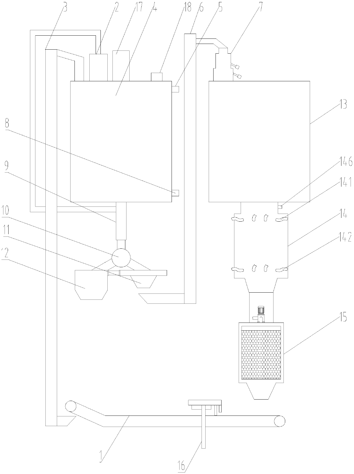
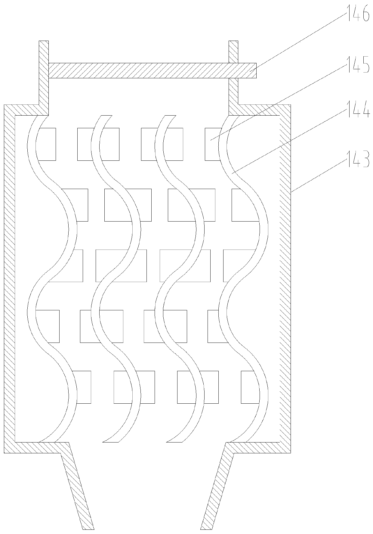
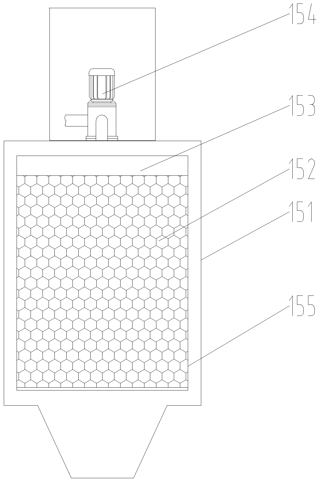
[0033] In order to make the object, technical solution and advantages of the present invention clearer, the present invention will be described in further detail below in conjunction with specific embodiments and with reference to the accompanying drawings.

[0034] It should be noted that all expressions using "first" and "second" in the embodiments of the present invention are to distinguish two entities with the same name but different parameters or parameters that are not the same, see "first" and "second" It is only for the convenience of expression, and should not be understood as limiting the embodiments of the present invention. In addition, the terms of direction and position mentioned in the present invention, such as "upper", "middle", "lower", "front", "rear", "Left", "right", "inner", "outer", "side", etc., are only referring to the directions and positions of the attached drawings. Therefore, the terms of directions and positions used are for explaining and unders...


PUM


Abstract

The invention discloses a slag removing and material supplementing device for a boiler. The slag removing and material supplementing device comprises the boiler, a first cooling assembly, a second cooling assembly, a conveying belt, a slag gallery, a first elevator, a feeder, a bulk machine and a vibration sieve, wherein the first cooling assembly is located on the lower part of the boiler and canpreliminarily cool slag discharged out of the boiler; the second cooling assembly is located on the lower part of the first cooling assembly and can secondarily cool the preliminarily cooled slag; the conveying belt can transfer secondarily cooled slag; the slag gallery can store the cooled slag; a loading inlet of the first elevator is located in the lower part of the other end of the conveyingbelt, a discharging outlet of the first elevator is located in the upper part of the slag gallery, and the transferred slag can be fed into the slag gallery by the first elevator; the feeder is located on the lower part of the slag gallery, a feeding inlet of the feeder communicates with the bottom of the slag gallery, and the slag in the slag gallery can be discharged; the bulk machine can load the discharged slag into a truck; and the vibration sieve can sieve fine sand in the slag, and the rest of the slag is recovered into the bulk machine. The slag removing and material supplementing device integrates slag removing and bed material supplementing, the material utilization rate is increased, the structure is simple, using is convenient and economical, and the manpower cost is saved.

Description

technical field [0001] The invention relates to the field of biomass combustion boilers, in particular to a boiler slag removal and feeding device. Background technique [0002] Biomass is a by-product of agricultural production, most of which are in low-efficiency utilization, that is, they are directly burned on wood stoves, and their conversion rate is only about 10%-20%, resulting in a large amount of exhaust heat loss and incomplete combustion of a large amount of gas. The method of bed combustion is used to improve the utilization rate of biomass. Add fine sand to the boiler, heat the fine sand to a fluidized state, and then add biomass. After the sand in the high-temperature fluidized state contacts with the biomass, the biomass Full combustion, the use of fluidized bed combustion has the advantage of high combustion efficiency. The inventors found that in the existing fluidized bed system, although the utilization efficiency of biomass has been improved, the bed mate...

Claims


Application Information

Patent Timeline
Patent Type & Authority Applications(China)
IPC IPC(8): F23C10/18F23C10/26F23C10/30B07B1/28B03C1/30
Inventor 刘宏
Owner 国祯美洁 (安徽)生物质热电有限公司
Why Eureka
Try Eureka