Air flow display method based on laser induced particle technology

A technology of air flow and display method, which is applied in the direction of aerodynamic test, machine/structural component test, measuring device, etc. It can solve the problems of unpublished patents, achieve uniform distribution, reduce complexity, and avoid environmental pollution Effect

Active Publication Date: 2019-06-11
NORTHWESTERN POLYTECHNICAL UNIV
View PDF8 Cites 5 Cited by
  • Summary
  • Abstract
  • Description
  • Claims
  • Application Information

AI Technical Summary

Problems solved by technology

Search for "laser-induced particle flow display" on the SooPAT patent search engine, but no relevant published patents are found

Method used


Image

  • Air flow display method based on laser induced particle technology
  • Air flow display method based on laser induced particle technology
  • Air flow display method based on laser induced particle technology

Examples


Embodiment Construction

[0028] Now in conjunction with embodiment, accompanying drawing, the present invention will be further described:

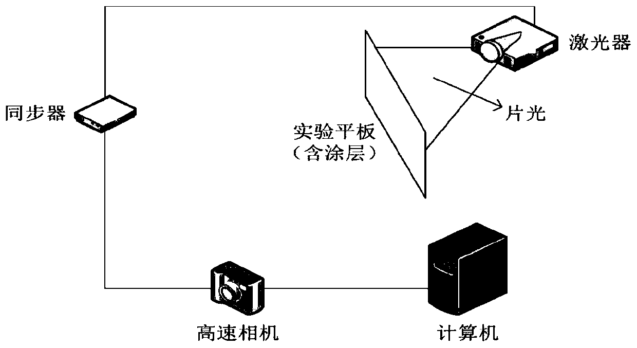
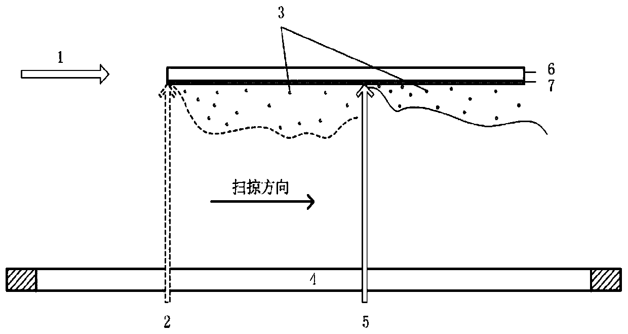
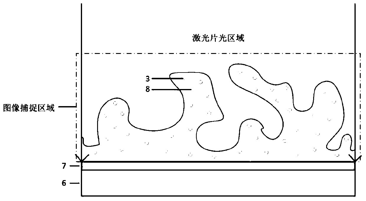
[0029] Laser particle induction technology is a "green" induction method that does not require any chemical agents. The induced particles are in the form of solid powder, small in size, easy to store, recyclable, and low in noise, which can avoid noise pollution and chemical agents. coming environmental pollution. And the laser can be transmitted through the optical fiber, which can conveniently realize long-distance operation and make the induction more thorough. In addition, laser induction technology is not limited by the material and type of the induced object, and can also selectively induce surface coating particles without damaging the surface of the material, with high efficiency. The principle is to adjust the energy density of the laser beam so that the energy density is higher than the highest energy threshold required to destroy the coating and lower...


PUM


Abstract

The invention relates to an air flow display method based on a laser induced particle technology, which organically combines the laser induced particle technology and a flow display technology. By adopting the laser induced particle technology, particles can be excited from the surface of an experimental model to realize the visualization of flow field information without introducing an additionalparticle generating device. The particles that are directly induced on the experimental model by using a laser particle induction technology are relatively evenly distributed in a flow field, so thatthe missing of local flow information caused by the uneven distribution of artificially added particles can be avoided, and the display of specific flows such as the boundary layer flow can be facilitated.

Description

technical field [0001] The invention relates to the field of flow display technology, in particular to design an air flow display method based on laser-induced particle technology that can be applied in a low-speed wind tunnel. Background technique [0002] The flow display method is a method of displaying flow phenomena with images on the premise of not changing the quality of the flow field and the properties of fluid mechanics. Such methods are commonly used in wind tunnels to visualize flow phenomena such as flow separation, wakes, vortices, boundary layers, and shock waves. The flow display method can be used in wind tunnel flow field measurement and various aerodynamic experiments. It provides reliable flow images for flow field analysis and calculation, and is conducive to the discovery of some new flow phenomena. It is an important research method in experimental fluid mechanics. Commonly used flow display methods include additive method, optical method, energy meth...

Claims


Application Information

Patent Timeline
Patent Type & Authority Applications(China)
IPC IPC(8): G01M9/02G01M9/06
Inventor 曹真李栋陆连山拜昱郑杰王文魁
Owner NORTHWESTERN POLYTECHNICAL UNIV
Why Eureka
Try Eureka