

Micro-strip navigation antenna with air back cavity
A microstrip and cavity-backed technology used in the field of satellite navigation antennas
- Summary
- Abstract
- Description
- Claims
- Application Information
AI Technical Summary
Problems solved by technology
Method used
Image

Examples
Embodiment Construction
[0018] The present invention will be described in further detail below in conjunction with the accompanying drawings and specific embodiments.
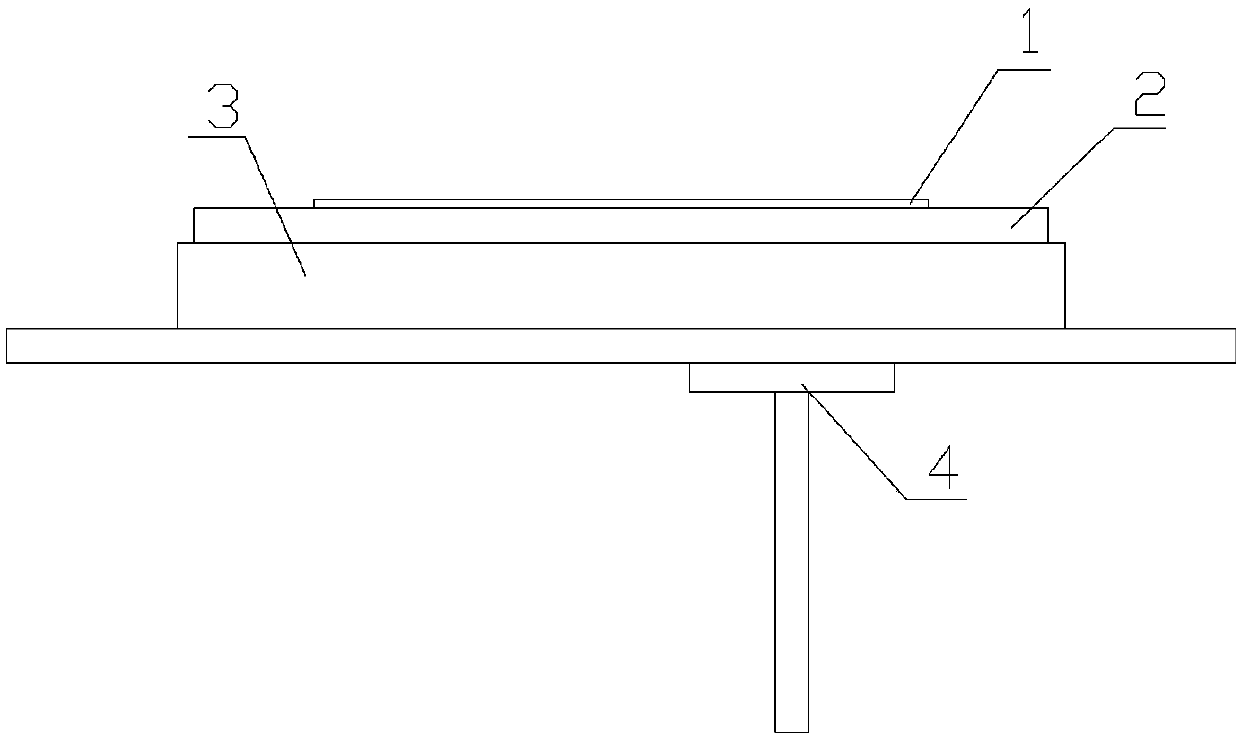
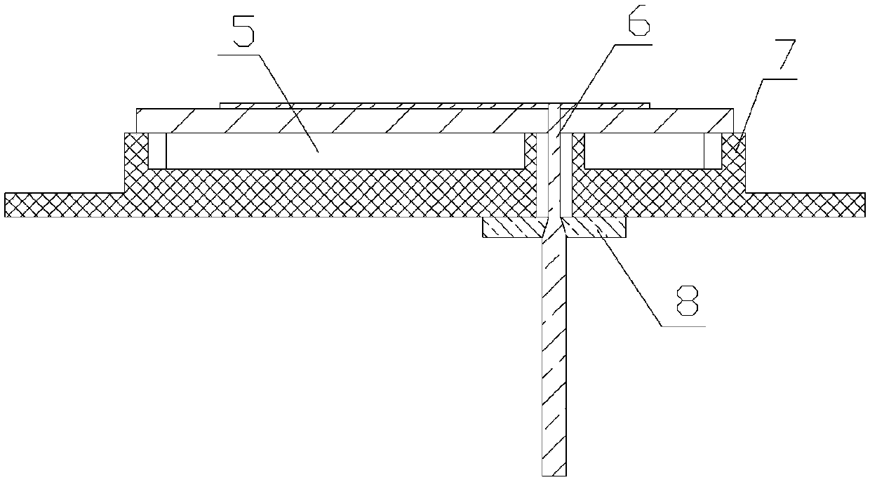
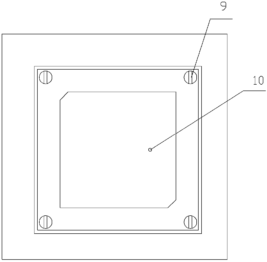
[0019] Such as Figure 1~3 As shown, a microstrip navigation antenna with an air-back cavity includes a microstrip printed board radiation layer radio frequency substrate 2, a structural cavity 3 and a feed connector 4, wherein the square structure of the microstrip printed board radiation layer The radio frequency substrate is installed in the structural cavity 3 through the mounting screws 9 of the radiation layer of the microstrip printed board, wherein the supporting walls around the structural cavity 3 form the outer wall structure of the structural cavity, and the inside of the structural cavity 3 is a groove structure, so that the structure The cavity 3 and the radio frequency substrate 2 of the microstrip printed board radiation layer of the flat structure form an air-backed cavity radiation layer 5; a metal pattern of the rad...
PUM
 Abstract
Description
Claims
Application Information