
Wall-mounted type active power filter and filtering compensation system thereof

A power filter and wall-mounted technology, which is applied in the field of active power filters and their filter compensation systems, can solve problems affecting the normal maintenance and use of active power filters, inconvenient removal and maintenance of active power filter cabinets, Inconvenient for active power filter cabinets and other issues, to achieve the effect of convenient short-distance movement, convenient heat dissipation or wiring, and convenient and stable suspension

Active Publication Date: 2019-06-11
浙江星明智能电气科技有限公司
View PDF5 Cites 0 Cited by
  • Summary
  • Abstract
  • Description
  • Claims
  • Application Information

AI Technical Summary

Problems solved by technology

[0005] The purpose of the present invention is to provide a wall-mounted active power filter to solve the problem that the wall-mounting of the existing active power filter proposed in the above-mentioned background technology is mostly inconvenient to remove the active power filter cabinet later Maintenance, thus affecting the normal maintenance and use of the active power filter, and at the same time it is inconvenient to temporarily transfer the position of the active power filter cabinet; our company is dedicated to solving power quality problems for users, and the active filter has unprecedented Comprehensive power quality management capabilities, the active power filter can filter out harmonics within the 2-50th order at the same time, the filtering ability can be as high as 97%, and the time for complete compensation of step-changing harmonics is 10ms shorter

Method used


Image

  • Wall-mounted type active power filter and filtering compensation system thereof
  • Wall-mounted type active power filter and filtering compensation system thereof
  • Wall-mounted type active power filter and filtering compensation system thereof

Examples

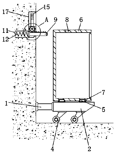
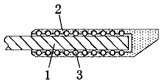

Embodiment Construction

[0026] The following will clearly and completely describe the technical solutions in the embodiments of the present invention with reference to the accompanying drawings in the embodiments of the present invention. Obviously, the described embodiments are only some, not all, embodiments of the present invention. Based on the embodiments of the present invention, all other embodiments obtained by persons of ordinary skill in the art without making creative efforts belong to the protection scope of the present invention.

[0027] see Figure 1-4 , the present invention provides a technical solution: a wall-mounted active power filter, including a beam bar 1, a roller 4 and a filter cabinet 6, the right side of the beam bar 1 is connected with a supporting bar 2, and the supporting bar The inner side of the support rod 2 is provided with a ball 3, and the ball 3 is located between the beam rod 1 and the support rod 2, the support rod 2 is a hollow structure, and the support rod 2...


PUM


Abstract

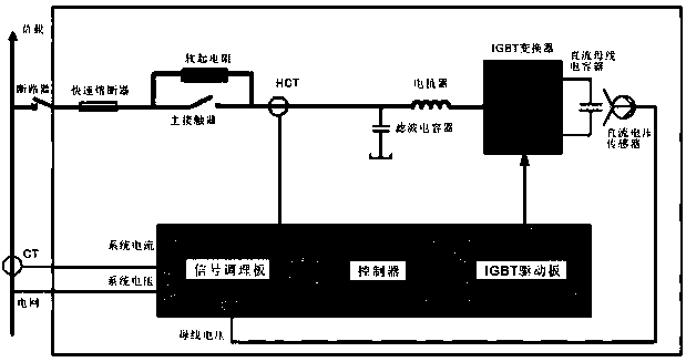
The invention discloses a wall-mounted type active power filter and a filtering compensation system thereof. The wall-mounted type active power filter comprises a cross beam rod, rolling wheels and afilter cabinet body, wherein a supporting rod is connected to the right side of the cross beam rod; a ball is arranged on the inner side of the supporting rod, and the ball is located between the cross beam rod and the supporting rod; the rolling wheels are installed below the supporting rod; a mounting-inserting block is arranged above the supporting rod; the filter cabinet body is arranged abovethe supporting rod, and a mounting-inserting groove is reserved below the filter cabinet body, the filter cabinet body is connected with the supporting rod through the mounting-inserting groove and the mounting-inserting block; a second mounting hole is formed in the connecting plate, and the connecting plate is positioned on the inner side of a containing groove; and the filtering compensation system consists of a signal conditioning plate, a controller, an IGBT driving plate, an IGBT converter, an electric reactor, a filter capacitor, a main contactor, a quick fuse and a circuit breaker which are sequentially connected in series.

Description

technical field [0001] The invention relates to the technical field of active power filters, in particular to a wall-mounted active power filter and a filter compensation system thereof. Background technique [0002] Active power filter is a kind of power electronic device, which is usually installed by rack installation or wall-mounted installation. In order to facilitate the maintenance of active power filter during daily operation, in addition to meeting local regulations, active power filter Sufficient space should be reserved at the inlet end of the device to facilitate the access of cables by maintenance personnel. The installation environment of the active power filter should ensure: convenient wiring, sufficient operating space, good ventilation, meeting heat dissipation requirements, and no corrosive gases , no dust particles, conductive dust, ambient humidity is less than 90%, ambient temperature in the range of 0-45 ℃, in line with fire protection requirements. ...

Claims


Application Information

Patent Timeline
Patent Type & Authority Applications(China)
IPC IPC(8): H02B1/40H02J3/01H02J3/18
CPCY02E40/20
Inventor 陈星亮
Owner 浙江星明智能电气科技有限公司
Learn More