Novel topology of double-stage matrix converter and common-mode voltage suppression strategy of double-stage matrix converter

A matrix converter and common-mode voltage technology, applied in the direction of converting AC power input to AC power output, converting AC power input to DC power output, electrical components, etc., can solve the problem of limited maximum voltage transmission ratio and limited voltage transmission ratio. Limitation, increase system loss and other issues, to achieve the effect of maintaining the quality of input current, reducing the number of actual switching, and changing the distribution of switching loss

Active Publication Date: 2019-06-11
CHINA UNIV OF MINING & TECH
View PDF5 Cites 9 Cited by
  • Summary
  • Abstract
  • Description
  • Claims
  • Application Information

AI Technical Summary

Problems solved by technology

[0003] In motor drive applications, the load side of the dual-stage matrix converter will generate a common-mode voltage, which in turn forms a shaft current, causing damage to the motor bearing and reducing the service life of the motor. At the same time, the common-mode voltage will generate a common-mode current in the system. Electromagnetic interference to the normal operation of the device
[0004] There have been related studies on the common-mode voltage suppression of dual-stage matrix converters. One method is to prevent the inverter stage from directly using zero vectors to participate in the synthesis of expected voltage vectors to achieve common-mode voltage suppression. For example, the rectifier stage has zero The vector inverter stage has no zero-vector modulation strategy, and the inverter stage uses two effective vectors in opposite directions to replace the zero vector, etc., but this type of method directly leads to the four-step commutation strategy that the rectifier stage must adopt, and the control is more complicated. The disadvantage of increasing the number of switching times increases the system loss, and the harmonic distortion rate of the input and output currents increases; another method is to change the sector distribution position of the rectifier stage, and use two smaller line voltages to synthesize the intermediate DC voltage to achieve Common-mode voltage suppression, but there is a problem that the maximum voltage transfer ratio is limited. At the same time, because the inverter stage has a zero vector, if the inverter stage uses a seven-segment switching sequence, the rectifier stage can achieve zero-current commutation, but the actual switching times If the seven-stage switching sequence is not used, the rectification stage must adopt a four-step commutation strategy
In summary, the existing modulation strategies for suppressing common-mode voltage have disadvantages such as complex commutation at the rectification stage, increased switching times, or limited voltage transfer ratio.

Method used


Image

  • Novel topology of double-stage matrix converter and common-mode voltage suppression strategy of double-stage matrix converter
  • Novel topology of double-stage matrix converter and common-mode voltage suppression strategy of double-stage matrix converter
  • Novel topology of double-stage matrix converter and common-mode voltage suppression strategy of double-stage matrix converter

Examples


Embodiment Construction

[0022] The present invention will be further described below in conjunction with accompanying drawing;

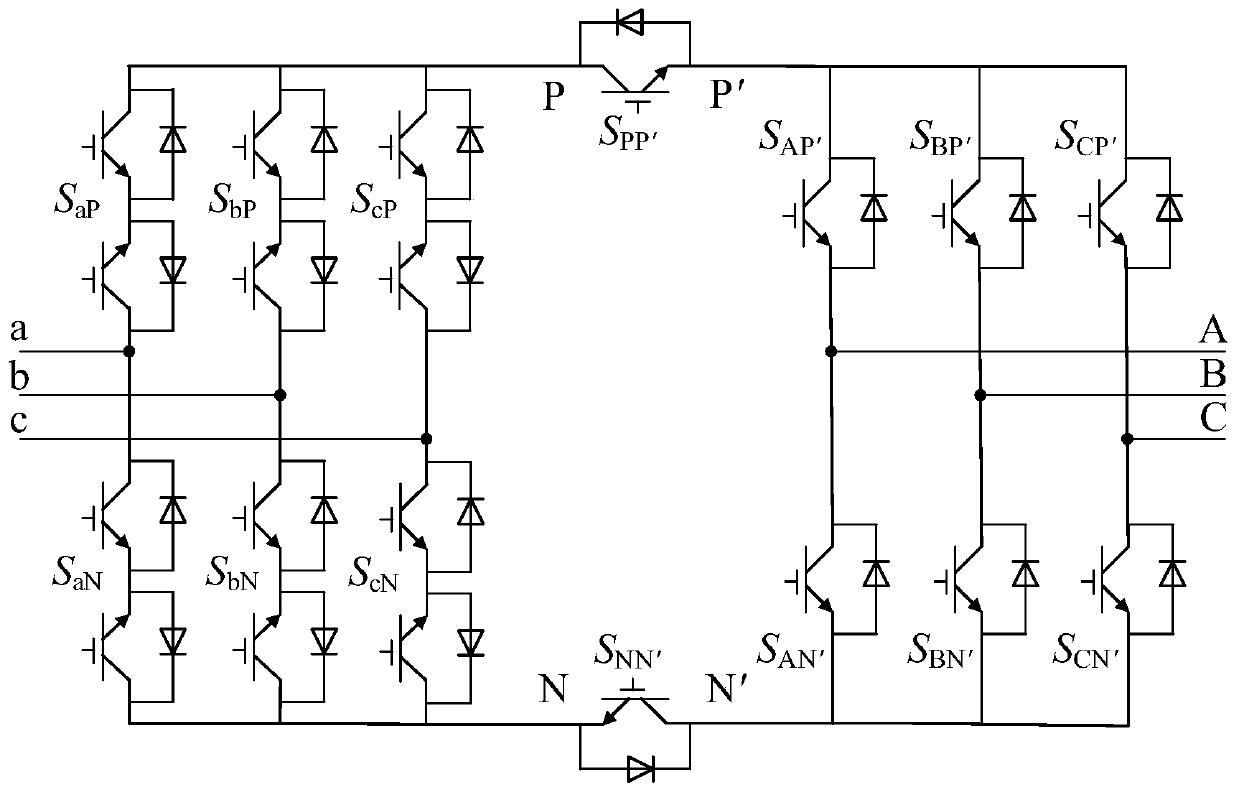
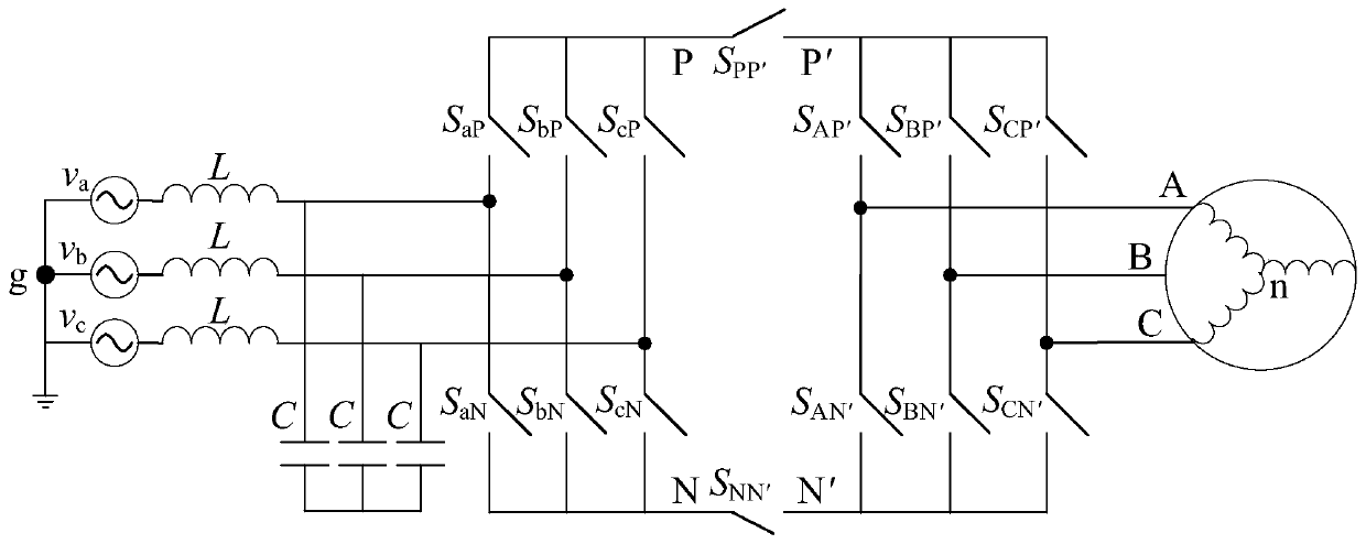
[0023] The new topology of a kind of two-stage matrix converter described in the present invention, as figure 1 As shown, the main circuit topology consists of three parts: rectifier stage, DC side and inverter stage. Among them, the three-phase input of the rectification stage is represented by a, b, and c. The rectification stage is a three-phase bridge circuit composed of six bidirectional switch units. Each bidirectional switch is connected in series by two unidirectional switch tubes of the common emitter stage. Formed, six bidirectional switch units with S ij (i=a, b, c; j=P, N) indicates that the input phase i is connected to the terminal j of the DC bus. A unidirectional switching tube is connected in series on the upper and lower DC busbars respectively, the emitter of the switching tube on the upper busbar is connected to the inverter stage, and the emitter of t...


PUM


Abstract

The invention discloses a novel topology of a double-stage matrix converter and a common-mode voltage suppression strategy of the double-stage matrix converter. According to the topological structure,a one-way switch tube is connected with a direct current side upper bus and a direct current side lower bus of a conventional double-stage matrix converter in series separately; when the direct-current side switch tube is switched off, the inversion-stage effective vector is equivalent to an inversion-stage zero vector when the direct-current side switch is switched on, and the inversion-stage zero vector is called as an inversion-stage equivalent zero vector; according to the novel topology, the equivalent zero vector is utilized to participate in modulation, and the inversion stage seven-section type space vector modulation is optimized into three-section space vector modulation, and meanwhile, the inhibition of common mode voltage is realized. The novel topology has the advantages thatthe common mode voltage of the load side can be reduced to be 0.577 times of the peak value of the input phase voltage in the whole area at the voltage transmission ratio of 0-0.866, and the inhibition effect is equivalent to that of the prior art; the current conversion control strategy is simple, the rectification stage can be directly subjected to current conversion, and the reliability of thesystem is improved; and the optimized modulation strategy is simple and easy to realize, the total actual switching frequency of the system is basically unchanged compared with that in a traditionalmodulation strategy, the actual switching frequency of the inversion stage is greatly reduced, the system switch loss distribution is changed, the output current harmonic distortion rate is lowered, the input current quality is kept unchanged, and the electric energy quality is improved.

Description

technical field [0001] The invention relates to a topology of a power electronic converter and a technology for suppressing a common-mode voltage, in particular to a new topology of a two-stage matrix converter and a strategy for suppressing a common-mode voltage. Background technique [0002] As a new type of AC-AC converter, the two-stage matrix converter not only has the advantages of traditional matrix converters, such as sinusoidal input and output currents, bidirectional energy flow, no need for DC energy storage elements, high power density, and compact structure, but also has the advantages of The advantages of zero-current commutation at the rectification level and simple control of the clamping circuit have attracted the attention of many scholars at home and abroad in the past 20 years, and it has great development potential. [0003] In motor drive applications, the load side of the dual-stage matrix converter will generate a common-mode voltage, which in turn fo...

Claims


Application Information

Patent Timeline
Patent Type & Authority Applications(China)
IPC IPC(8): H02M5/458H02M7/219H02M7/5387H02M1/12
Inventor 戴鹏李景杰常文宇王晨晖公铮张海军吕文健
Owner CHINA UNIV OF MINING & TECH
Why Eureka
Try Eureka