Double-mechanical arm calibration method based on camera optical axis constraint

A dual manipulator and calibration method technology, applied in the field of robot calibration, can solve the problems of lower absolute positioning accuracy of the end of the manipulator, kinematic parameter error, complex calibration process, etc., and achieves reduced calibration costs, fewer calibration steps, and calibration accuracy. high effect

Active Publication Date: 2019-06-14
HARBIN ENG UNIV
View PDF8 Cites 17 Cited by
  • Summary
  • Abstract
  • Description
  • Claims
  • Application Information

AI Technical Summary

Problems solved by technology

For a dual-manipulator system, generally only the base coordinates are calibrated, and due to factors such as manufacturing tolerances, environmental changes, and wear, there are errors between the actual kinematic parameters of the manipulator and the nominal kinematic parameters set by the factory, resulting in the end of the manipulator Absolute positioning accuracy is reduced, so kinematic parameter calibration is required
At present, the calibration of the kinematic parameters of the manipulator and the calibration of the base coordinate system usually use high-precision measuring instruments or elaborate calibration tools. Such methods are expensive and require professional personnel to operate, and are not suitable for simple and effective calibration in most scenarios. Requirements, and the calibration of the kinematics parameters of the manipulator and the calibration of the base coordinates are usually carried out separately, using different calibration equipment and calibration methods, which makes the calibration process more complicated

Method used


Image

  • Double-mechanical arm calibration method based on camera optical axis constraint
  • Double-mechanical arm calibration method based on camera optical axis constraint
  • Double-mechanical arm calibration method based on camera optical axis constraint

Examples


Embodiment Construction

[0037] The present invention will be described in detail below in conjunction with the accompanying drawings.

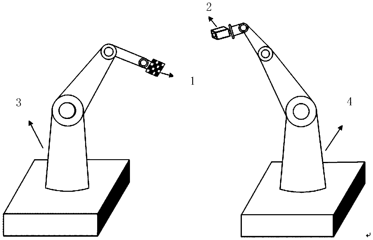
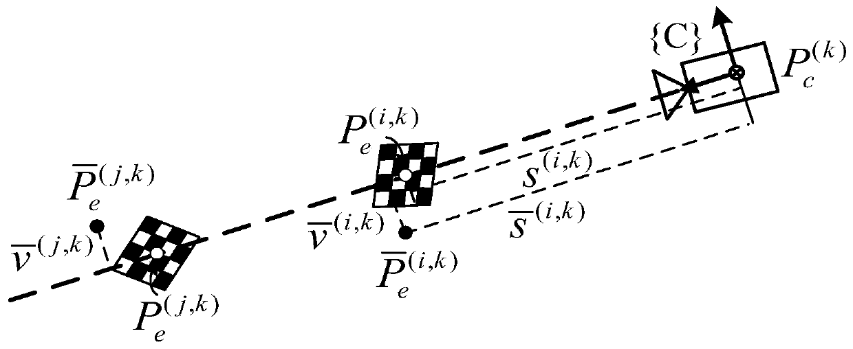
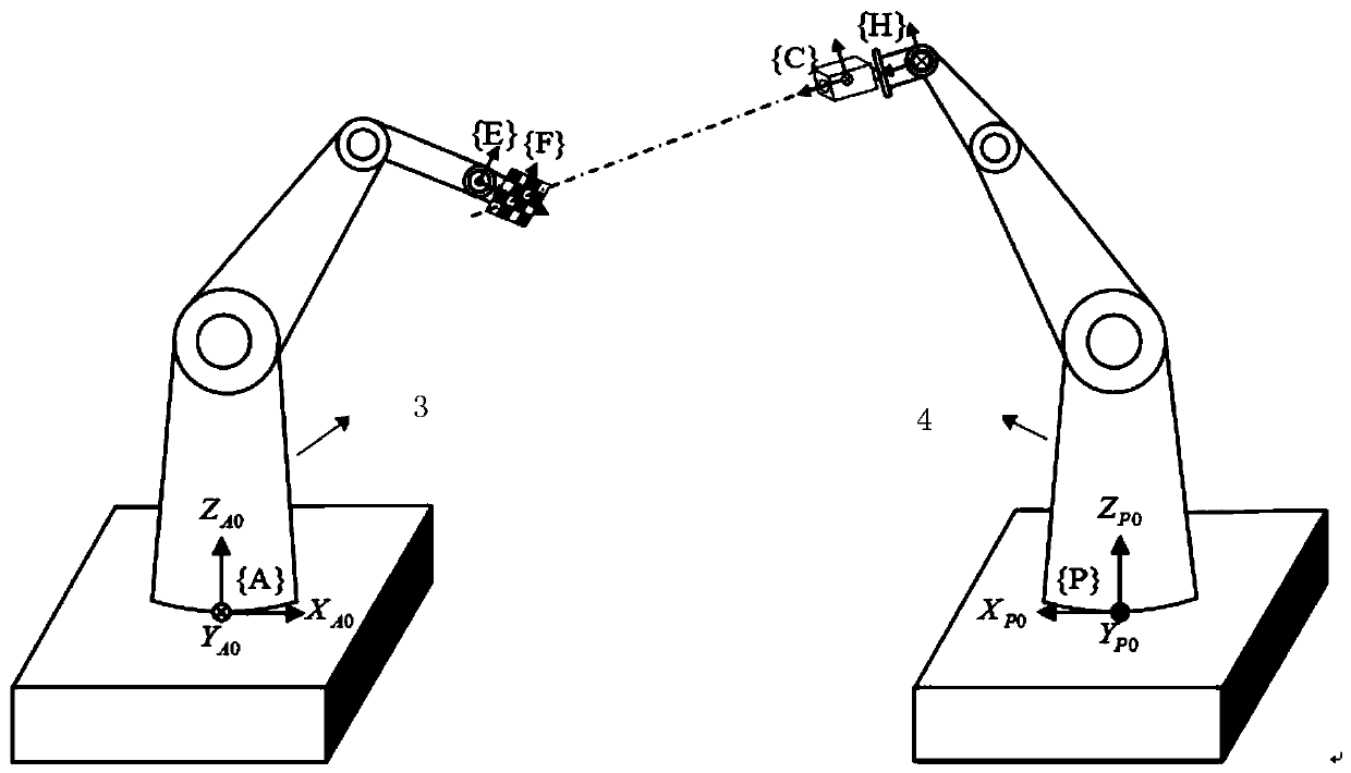
[0038] The invention provides a method for calibrating dual mechanical arms based on camera optical axis constraints. At present, robots are developing rapidly, and more and more fields require dual-arm collaborative robots. In order to successfully complete the operation tasks, the dual-arm system must be calibrated. In view of the low positioning accuracy of the current dual-arm collaborative robot, the present invention simultaneously completes the calibration of kinematic parameters and base coordinates of the two robotic arms, providing technical support for the dual-arm system to complete high-precision tasks. The basic idea of ​​the present invention is to make the optical axis of the camera installed at the end of one manipulator serve as a virtual linear constraint, and the pose of the other end of the manipulator satisfy the virtual constraint of the optica...


PUM


Abstract

The invention relates to a double-mechanical arm calibration method based on camera optical axis constraint. The double-mechanical arm calibration method comprises the following steps that firstly, adouble-mechanical arm calibration system is established; secondly, a parameter calibration equation based on an error model is established; thirdly, feature point alignment and position data based onvisual control is acquired; and fourthly, the calibration equation is solved. According to the double-mechanical arm calibration method, the double-mechanical arm calibration system is established only through a camera and a checkerboard calibration plate, operation is easy and convenient, an expensive high-precision instrument and an elaborate calibration tool are not needed, and the calibrationcost is reduced; the calibration precision is higher, the number of the calibration steps is smaller, and the operation is more convenient; a visual control method based on images is used for controlling movement of a drive mechanical arm, feature points are automatically aligned to a camera optical axis, professional operation is not needed in the calibration process, and only an operator is needed to carry out simple supervision; and the double-mechanical arm calibration method is suitable for various double-arm cooperative systems and high in calibration precision, and a calibration resultcan meet requirements of most double-arm cooperative tasks.

Description

technical field [0001] The invention relates to a dual-manipulator calibration method, in particular to a dual-manipulator calibration method based on camera optical axis constraints, and belongs to the field of robot calibration. Background technique [0002] As one of the major landmark products in the development of the robot industry, the dual-arm robot has more and more applications in the fields of industry, life, medical treatment, aerospace and other fields. Dual robotic arms can cooperate to complete tasks that are difficult for a single robotic arm, such as moving objects with large mass or volume, complex assembly of multiple components, handling of flexible objects, etc., which has the advantages of saving cost, saving space, and improving production efficiency. When the dual-arm cooperation completes various tasks, the accuracy of the dual-arm system directly affects the degree of completion and success rate of the task, and tasks such as parts assembly put forw...

Claims


Application Information

Patent Timeline
Patent Type & Authority Applications(China)
IPC IPC(8): B25J9/16
Inventor 朱齐丹谢心如李超夏桂华蔡成涛
Owner HARBIN ENG UNIV
Why Eureka
Try Eureka