Waste disposal device with functions of energy saving and emission reduction

A waste treatment device, energy saving and emission reduction technology, applied in the direction of combustion method, combustion type, incinerator, etc., can solve the problems of increasing incineration time, inapplicability, energy consumption, etc., achieve high efficiency of waste incineration, reduce slag discharge, The effect of reducing fuel consumption

Active Publication Date: 2019-06-14
HEFEI REYAO ENVIRONMENTAL PROTECTION BUILDING MATERIAL TECH
View PDF7 Cites 0 Cited by
  • Summary
  • Abstract
  • Description
  • Claims
  • Application Information

AI Technical Summary

Problems solved by technology

Existing crushing devices for crushing rubbish generally shred the rubbish through the interaction of two rollers with hobbing teeth. Since the distance between the rollers remains unchanged, it is not suitable for large-sized At the same time, it adopts the method of shredding, and the crushing of garbage can only achieve preliminary crushing, and th

Method used


Image

  • Waste disposal device with functions of energy saving and emission reduction
  • Waste disposal device with functions of energy saving and emission reduction
  • Waste disposal device with functions of energy saving and emission reduction

Examples


Example Embodiment

[0030] Example 1

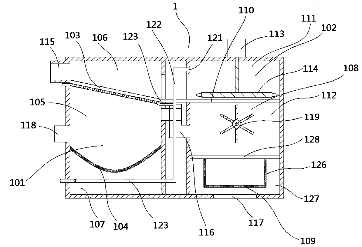
[0031] A garbage treatment device with energy-saving and emission reduction functions includes an incinerator 1 and a garbage crushing and grinding device. The garbage crushing and grinding device is a garbage crushing device on the existing market, which is installed in front of the incinerator 1, so that the garbage enters Before the incinerator 1 is crushed and ground, the adequacy of the subsequent incineration in the incinerator 1 is ensured.

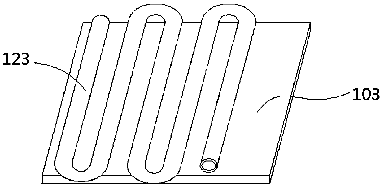
[0032] Such as figure 1 As shown, the incinerator 1 in the system has a special structural design, which includes a pretreatment chamber 101 and an incineration chamber 102. The pretreatment chamber 101 is sequentially provided with first filter plates 103 and The downwardly recessed arc-shaped aluminum plate 104, the first filter plate 103 and the arc-shaped aluminum plate 104 separate the pretreatment chamber 101 from top to bottom into a large particle garbage chamber 105, a dust garbage chamber 106, and a water st...

Example Embodiment

[0039] Example 2

[0040] The garbage treatment device in this embodiment includes a garbage crushing device 2, such as Figure 7 , Figure 8 As shown, the garbage crushing device 2 includes a crushing housing 201, and the crushing housing 201 forms a crushing chamber 221 with a square cross section.

[0041] In the crushing shell 201, that is, the crushing chamber 221 is provided with longitudinally arranged rollers 204 and crushed bodies 205 respectively distributed on the left and right sides of the rollers 204. The rollers 204 keep rotating under the action of the motor. The crushed bodies 205 include A circular arc plate 206 that performs a horizontal linear reciprocating motion and has a circular arc-shaped cross section. The length of the circular arc plate 206 is arranged longitudinally and the open end of the circular arc plate 206 faces the roller 204. The inner wall of the circular arc plate 206 is fixed with the roller 204 The outer wall cooperates with the grinding blo...

Example Embodiment

[0051] Example 3

[0052] Same as Embodiment 1 and Embodiment 2, the garbage disposal device in this embodiment includes the incinerator 1 in Embodiment 1, and includes the garbage crushing device 2 in Embodiment 2, and replacing the garbage crushing device 2 in Embodiment 1. Mentioned common garbage crushing and grinding devices on the existing market.


PUM


Abstract

The invention relates to a waste disposal device, and discloses a waste disposal device with the functions of energy saving and emission reduction. The waste disposal device comprises a waste crushingdevice (2) comprising a crushing shell (201), and the crushing shell (201) is internally provided with a roller (204) arranged longitudinally, and crushing bodies (205) arranged on the right and leftsides of the roller (204) separately; each crushing body (205) comprises a crushing block (207) matched with the outside wall of the roller (204) for crushing wastes, and the roller (204) and the side faces, close to the roller (204), of the right and left crushing blocks (207) form a waste crushing cavity (208) jointly; and the width of the crushing block (207) is increased from top to bottom gradually so that the width of the waste crushing cavity (208) is decreased from top to bottom gradually. According to the waste disposal device, through design of the waste crushing device, wastes canbe crushed more thoroughly, so that the waste incineration efficiency is higher, and the fuel consumption is reduced; the combustion is more thorough, and slag emission is reduced; and the effects ofenergy saving and emission reduction are achieved fully.

Description

technical field [0001] The invention relates to a garbage disposal device, in particular to a garbage disposal device with the function of energy saving and emission reduction. Background technique [0002] Garbage is solid waste generated in human daily life and production. Due to the large amount of discharge, complex and diverse components, and polluting, resourceful and social nature, it needs harmless, resourceful, reduction and socialized treatment. If not handled properly, it will pollute the environment, affect environmental sanitation, waste resources, destroy production and living safety, and disrupt social harmony. [0003] At present, the municipal solid waste treatment methods widely used at home and abroad mainly include sanitary landfill, high-temperature composting and incineration, etc. The proportions of these three main waste treatment methods vary due to factors such as geographical environment, waste composition, and economic development level. Among th...

Claims


Application Information

Patent Timeline
IPC IPC(8): F23G5/033F23G5/44F23G5/50
Inventor 刘莎
Owner HEFEI REYAO ENVIRONMENTAL PROTECTION BUILDING MATERIAL TECH
Why Eureka
Try Eureka