Testing device for semiconductor thermoelectric refrigerating unit

A thermoelectric cooler and testing device technology, which is applied in the direction of single semiconductor device testing, etc., can solve the problems of lack of quantitative testing equipment for thermoelectric cooling devices, failure to consider the use of equipment for heat leakage and heat conduction, rough qualitative testing, etc.

Inactive Publication Date: 2019-06-14
GUILIN UNIV OF ELECTRONIC TECH
View PDF5 Cites 1 Cited by
  • Summary
  • Abstract
  • Description
  • Claims
  • Application Information

AI Technical Summary

Problems solved by technology

[0003] Obtain the maximum cooling capacity per unit time when a certain semiconductor thermoelectric cooler product is actually working Q c,max And the maximum temperature difference between cold and hot ends Δ T max , optimal current and other parameters are very meaningful for the design and manufacture of semiconductor thermoelectric cooler products and practical use. Existing manufacturers only calculate these parameters based on the temperature difference between the hot and cold plates of the thermoelectric cooler and the electrical parameters plus theoretical calculations. This semi-theoretical estimate does not take into account the heat leakage and heat conduction of the equipment used, and can only conduct a rough qualitative test for semiconductor thermoelectric cooler products. At present, there is still a lack of quantitative testing equipment for thermoelectric refrigeration devices in the industry.

Method used


Image

  • Testing device for semiconductor thermoelectric refrigerating unit
  • Testing device for semiconductor thermoelectric refrigerating unit

Examples


Embodiment Construction

[0023] The present invention will be described in detail below in conjunction with the accompanying drawings.

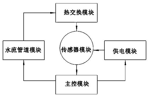
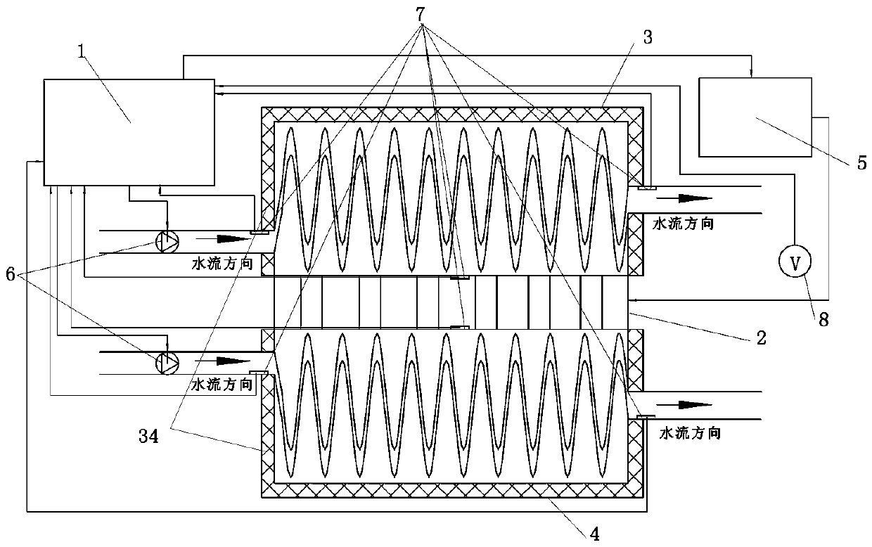
[0024] refer to Figure 1-2 , a test device for a semiconductor thermoelectric refrigerator, including a main control module, a heat exchange module, a liquid medium pipeline module, a power supply module, and a sensor module,

[0025] In this embodiment, the liquid medium is water, and the main control module is computer 1;

[0026] The heat exchange module communicates with the water flow pipeline module, and the water flow pipeline module, the power supply module, and the sensor module are respectively electrically connected to the computer 1;

[0027] The water flow pipeline module includes a hot-end water flow pipeline and a cold-end water flow pipeline, and a power pump 6 controlled by a computer 1 is arranged in the hot-end and cold-end water flow pipelines;

[0028] The heat exchange module includes a hot end exchanger 3 and a cold end exchanger 4. The hot ...


PUM


Abstract

The invention belongs to the technical field of semiconductor thermoelectricity, and particularly relates to a testing device for a semiconductor thermoelectric refrigerating unit. The testing devicecomprises a main control module, a heat exchange module, a liquid medium pipeline module, an electricity supply module and a sensor module; the heat exchange module comprises a hot end exchanger and acold end exchanger, the hot end exchanger and the cold end exchanger are each provided with a liquid medium outlet and a liquid medium inlet, the liquid medium outlets and the liquid medium inlets are provided with temperature sensors correspondingly, the hot end exchanger and the cold end exchanger are provided with heat exchanging faces making contact with the cold end and the hot end of the semiconductor thermoelectric refrigerating unit, and heat-insulation layers are arranged on the outer surfaces, except for the outer surfaces of the heat exchanging faces and the liquid medium outlet and the liquid medium inlet, of the hot end exchanger and the cold end exchanger correspondingly; the liquid medium pipeline module is provided with a power pump controlled by the main control module; the electricity supply module comprises a direct-current electricity source controlled by the main control module; and the main control module is a computer. The testing device works through a water flow heat metering method, the heat exchange module in heat insulation with the exterior is adopted, thus heat emission in testing can be effectively prevented, and the measurement error can be effectively reduced.

Description

technical field [0001] The invention belongs to the technical field of semiconductor thermoelectricity, and in particular relates to a testing device for a semiconductor thermoelectric refrigerator. Background technique [0002] Thermoelectric refrigeration is a current refrigeration technology, which uses the Peltier effect of semiconductor bismuth telluride materials to transfer heat from one side of the material to the other side, forming a temperature difference, and achieving local cooling. [0003] Obtain the maximum cooling capacity per unit time when a certain semiconductor thermoelectric cooler product is actually working Q c,max And the maximum temperature difference between cold and hot ends Δ T max , optimal current and other parameters are very meaningful for the design and manufacture of semiconductor thermoelectric cooler products and practical use. Existing manufacturers only calculate these parameters based on the temperature difference between the hot an...

Claims


Application Information

Patent Timeline
Patent Type & Authority Applications(China)
IPC IPC(8): G01R31/26
Inventor 胡晓凯杨道国
Owner GUILIN UNIV OF ELECTRONIC TECH
Why Eureka
Try Eureka