Obstacle detecting method and device and unmanned aerial vehicle

A technology for obstacle detection and drones, applied in the field of drones, can solve the problems of poor detection effect and the accuracy of obstacle detection under the stability of drones, and achieve the effect of improving accuracy

Pending Publication Date: 2019-06-14
SHENZHEN AUTEL INTELLIGENT AVIATION TECH CO LTD
View PDF0 Cites 5 Cited by
  • Summary
  • Abstract
  • Description
  • Claims
  • Application Information

AI Technical Summary

Problems solved by technology

However, the matching accuracy of binocular vision is greatly affected by the ambient light and the texture of the detected object. The existing obstacle detection equipment based on binocular vision has poor detection effect in weak or repeated texture environments, which greatly affects Improve the stability of the drone when working indoors and the accuracy of obstacle detection below when landing on non-textured ground such as tile cement
[0005] Therefore, the existing obstacle detection technology still needs to be improved and developed

Method used


Image

  • Obstacle detecting method and device and unmanned aerial vehicle
  • Obstacle detecting method and device and unmanned aerial vehicle
  • Obstacle detecting method and device and unmanned aerial vehicle

Examples


Embodiment 1

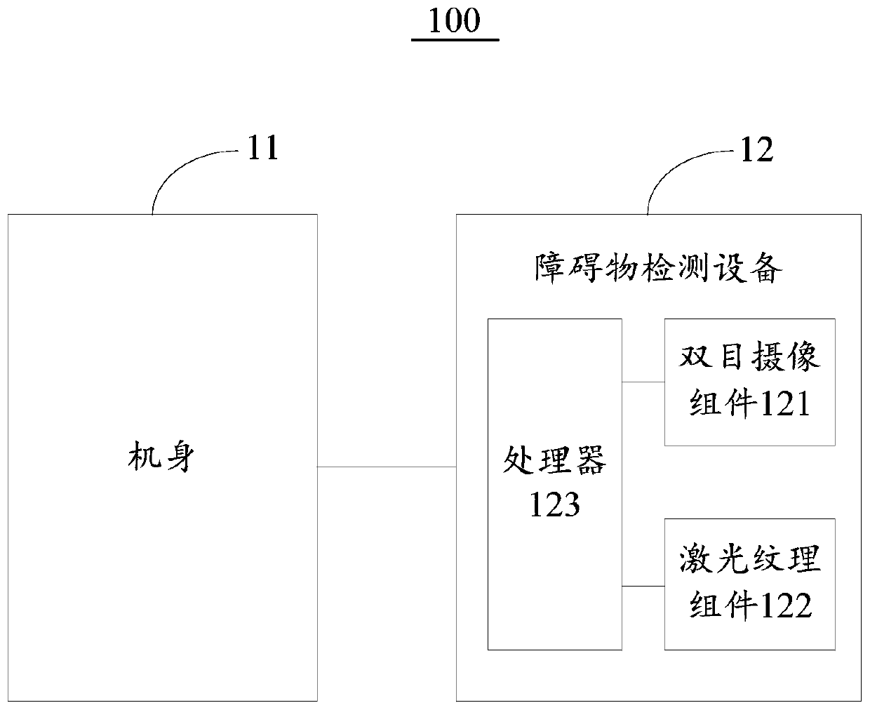
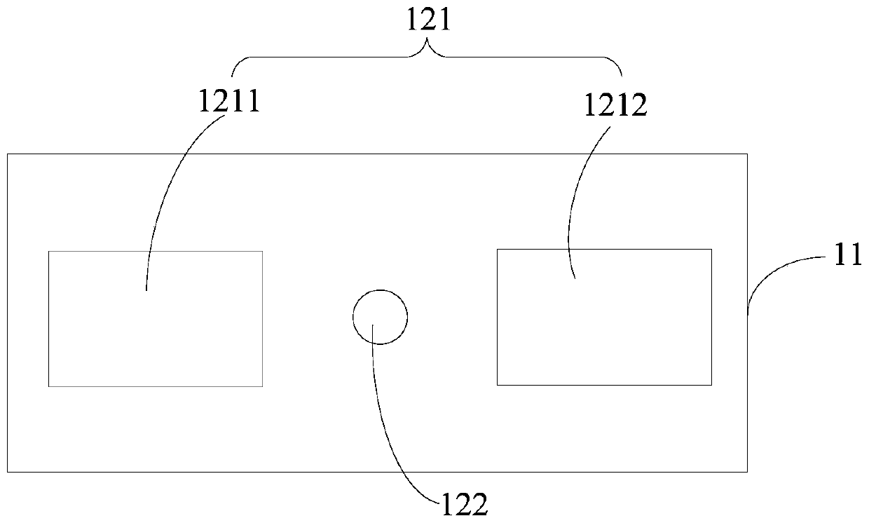
[0099] see figure 1 , is a hardware block diagram of an unmanned aerial vehicle provided by an embodiment of the present invention. The unmanned aerial vehicle 100 includes: a fuselage 11, an arm connected to the fuselage, a power device arranged on the arm, and an The obstacle detection device 12 of the body 11. The number of arms is at least two, and the arms can be fixedly connected, integrally formed or detachably connected to the fuselage 11 . The power unit usually includes a motor located at the end of the arm and a propeller connected to the motor, and the power unit is used to provide lift or flight power for the drone to fly.

[0100] Wherein, the fuselage 11 is the main body of the UAV 100, on which various functional parts of the UAV 100 (for example, the landing gear used to support the UAV 100, etc. ) and various functional circuit components of the drone 100 (for example, Micro-programmed Control Unit (MCU), Digital Signal Processor (Digital Signal Processor, ...

Embodiment 2

[0120] Image 6 It is a schematic flow chart of an obstacle detection method provided by an embodiment of the present invention, which can be applied to any movable carrier with a binocular camera component and a laser texture component, for example, as figure 1 A drone 100 is shown.

[0121] Specifically, see Image 6 , the method may include but not limited to the following steps:

[0122] Step 110: Start the laser texture component to emit laser texture.

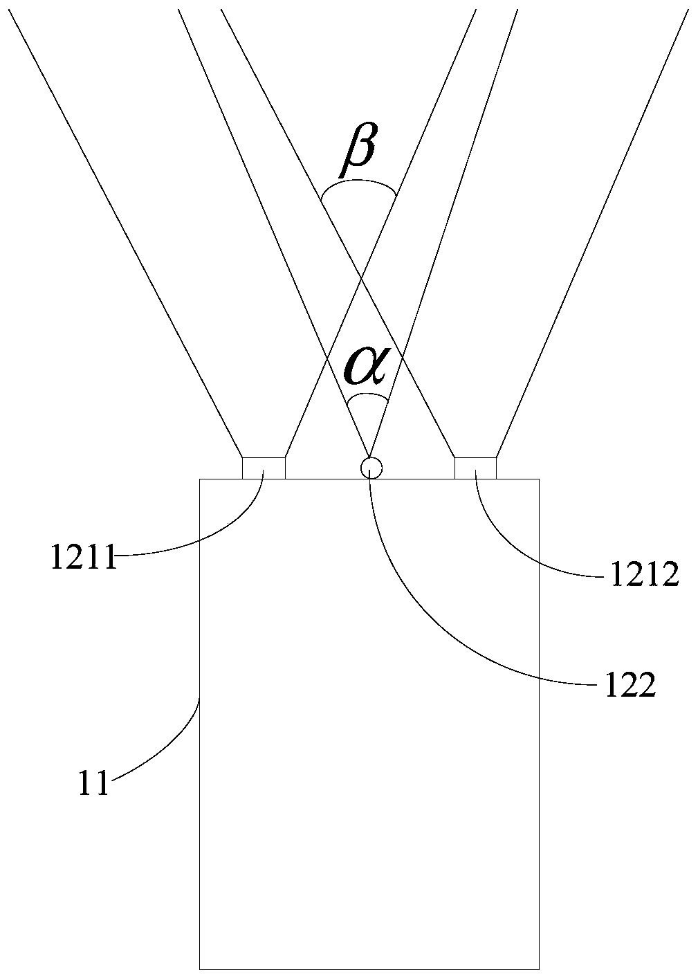
[0123] As mentioned above, the laser texture component is used to emit the laser texture that can be sensed by the binocular camera component. The projection range of the laser texture component may partially or completely cover the binocular viewing angle range of the binocular camera component. Therefore, the laser texture emitted by the laser texture component can fill the area with sparse texture in the shooting scene of the binocular camera component, and enhance the texture of the shooting scene of the binocular...

Embodiment 3

[0133] In an application scenario that requires high obstacle detection accuracy, for example, when the drone lands, you can refer to the obstacle detection method described in the second embodiment above, and start the laser texture component throughout the process to emit laser texture . However, in some other applications, for example, when the scene texture is rich and the light is sufficient, only conventional binocular sensing (that is, no need for laser components to emit laser texture) can also achieve higher barriers object detection accuracy.

[0134] Therefore, in order to reduce the energy consumption of the obstacle detection device while ensuring the accuracy of obstacle detection, the embodiment of the present invention also provides another obstacle detection method. This method is different from the obstacle detection method described in Embodiment 2 in that: before starting the laser texture component to emit laser textures, it is first determined to turn on...


PUM


Abstract

The embodiments of the invention relate to the technical field of unmanned aerial vehicles, and particularly disclose an obstacle detecting method and device and an unmanned aerial vehicle. The unmanned aerial vehicle comprises a binocular camera assembly and a laser texture assembly. The detecting method comprises the steps that starting of the laser texture assembly is determined; the laser texture assembly is started to emit laser texture; binocular views containing the laser texture collected by the binocular camera assembly are obtained, the binocular views containing the laser texture collected by the binocular camera assembly are set as target binocular views; and obstacle detection is carried out based on the target binocular views. According to the technical scheme, under the condition that an original binocular matching algorithm and structure are not changed, the binocular three-dimensional matching precision is improved, and the precision of the obstacle detection is further improved; and meanwhile, the unmanned aerial vehicle can further perform binocular sensing during night flight.

Description

technical field [0001] Embodiments of the present invention relate to the technical field of unmanned aerial vehicles, and in particular, to an obstacle detection method and device, and an unmanned aerial vehicle. Background technique [0002] UAV is an unmanned aircraft that controls the flight attitude through radio remote control equipment and built-in programs. Because of its advantages such as flexible maneuvering, quick response, unmanned driving, and low operating requirements, it has been widely used in aerial photography, Plant protection, power inspection, disaster relief and many other fields. [0003] As the application of drones becomes more and more extensive, the external environment that drones need to deal with is becoming more and more complex, and the obstacles that drones may encounter are also increasing. At present, in order to ensure flight safety, UAVs are generally equipped with obstacle detection equipment. [0004] At present, in order to meet th...

Claims


Application Information

Patent Timeline
Patent Type & Authority Applications(China)
IPC IPC(8): G05D1/02
CPCG06V20/17G06V10/25G06V10/80B64C39/024B64D45/08G05D1/101H04N2013/0081H04N13/254B64U2101/30H04N13/296H04N13/239G06V20/58B64D47/00G01J1/4204B64U2101/00
Inventor 郑欣
Owner SHENZHEN AUTEL INTELLIGENT AVIATION TECH CO LTD
Why Eureka
Try Eureka