
A machine vision image correction method for on-line detection

An image correction and machine vision technology, applied in image analysis, image enhancement, image data processing, etc., can solve problems such as large error in correction results, inaccurate detection results, and many parameter settings, and achieve high-precision correction and large-scale The effect of high range and correction efficiency

Active Publication Date: 2022-03-25
UNIV OF SHANGHAI FOR SCI & TECH
View PDF5 Cites 0 Cited by
  • Summary
  • Abstract
  • Description
  • Claims
  • Application Information

AI Technical Summary

Problems solved by technology

At present, the algorithms for correcting distorted images generally use technologies such as line detection and rotation angle detection, but due to the large number of parameter settings, the program is relatively cumbersome, and when the tilt angle of the camera installation changes, the line detection system will also fail due to the fixed parameters. cause inaccurate test results
In addition, the traditional image transformation needs to extract the objects on the processed surface, which brings in the original processing error, which makes the error of the correction result too large

Method used


Image

  • A machine vision image correction method for on-line detection
  • A machine vision image correction method for on-line detection
  • A machine vision image correction method for on-line detection

Examples


Embodiment Construction

[0033] In order to make the technical means and effects realized by the present invention easy to understand, the present invention will be described in detail below with reference to the embodiments and the accompanying drawings.

[0034] Example:

[0035] This embodiment provides a machine vision image correction method for online detection, comprising the following steps:

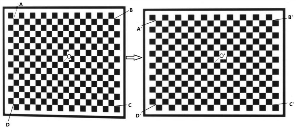
[0036] Step 1, use an industrial camera and lens to obtain the image of the checkerboard calibration plate and the laser processing image of the workpiece on the same plane as the checkerboard calibration plate. The image directly obtained by the industrial camera is the distorted image located in the distorted coordinate system. After the image is corrected, a standard image in the standard coordinate system is obtained.

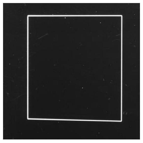
[0037] The laser-processed image in this example is a 20 mm square laser-processed image.

[0038] The accuracy of the checkerboard calibration board in step 1 is 1um.

[0039] The...


PUM


Abstract

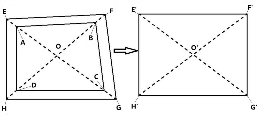
The invention provides a machine vision image correction method for on-line detection, which includes the following steps: Step 1, using an industrial camera and a lens to obtain the image of the checkerboard calibration plate and the laser processing image of the workpiece as a distorted image, correcting the distortion After the image is corrected, a standard image in the standard coordinate system is obtained; step 2, adjust the field of view of the industrial camera so that the laser processing image and the checkerboard calibration board are all within the field of view; step 3, take the 4 corner points of the checkerboard calibration board and the center corner point, extract the feature points E, F, G and H points of the distorted image through the corner point and the center corner point; step 4, determine the coordinates of E, F, G and H points in the standard image; step 5, according to Set of linear equations: R=SF to solve F; step 6, obtain the transformation matrix T according to F and convert the points in the distorted coordinate system into points in the standard coordinate system through the transformation matrix to obtain the standard image; step 7, the standard image The image is cropped and the image correction is completed.

Description

technical field [0001] The invention belongs to the field of machine vision online detection, in particular to a machine vision image correction method for online detection. Background technique [0002] Due to the influence of the installation position of processing systems such as lasers, the imaging system sometimes needs to be installed obliquely to achieve online measurement, which will distort the image captured by the camera, and the image can be further processed by correcting the distorted image into an orthographic projection. At present, the algorithms for distorted image correction generally use technologies such as line detection and rotation angle detection. However, due to the large number of parameter settings, the program is cumbersome, and when the camera installation tilt angle changes, the line detection system will also be due to the fixed parameters. result in inaccurate test results. In addition, the traditional image transformation needs to extract t...

Claims


Application Information

Patent Timeline
Patent Type & Authority Patents(China)
IPC IPC(8): G06T7/80G06T5/00
Inventor 陈光胜田培运
Owner UNIV OF SHANGHAI FOR SCI & TECH
Learn More