An SLAM map splicing method and system

A map and sub-map technology, applied in the field of SLAM map stitching methods and systems, can solve the problems of SLAM tracking loss and mapping failure.

Active Publication Date: 2019-06-14
GUANGZHOU XIAOPENG MOTORS TECH CO LTD
View PDF8 Cites 30 Cited by
  • Summary
  • Abstract
  • Description
  • Claims
  • Application Information

AI Technical Summary

Problems solved by technology

[0003] The embodiment of the present invention discloses a SLAM map splicing method and system, which can solve the problem of SLAM t

Method used


Image

  • An SLAM map splicing method and system
  • An SLAM map splicing method and system
  • An SLAM map splicing method and system

Examples


Embodiment 1

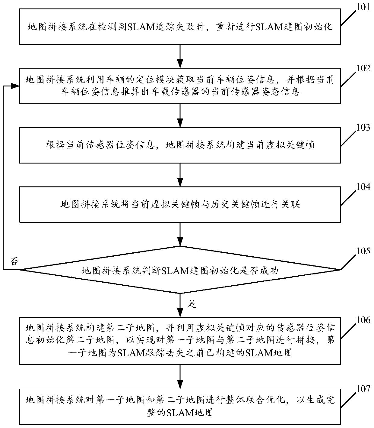
[0065] see figure 1 , figure 1 It is a schematic flowchart of a SLAM map mosaic method disclosed in an embodiment of the present invention. like figure 1 As shown, the SLAM map stitching method is applied to a map stitching system, and may specifically include the following steps.

[0066] 101. When the map stitching system detects that SLAM tracking is lost, it re-initializes SLAM mapping.

[0067] The embodiment of the present invention is applicable to visual SLAM mapping and laser SLAM mapping. Taking visual SLAM mapping as an example to illustrate, visual SLAM mapping mainly includes the following steps:

[0068] The front-end performs feature point matching on adjacent image frames based on the image frames continuously collected by the vehicle-mounted sensor. The vehicle-mounted sensor can be a vehicle-mounted camera, specifically a monocular camera, a binocular camera, or a depth camera. limited. Optionally, for a monocular camera, according to the feature point ...

Embodiment 2

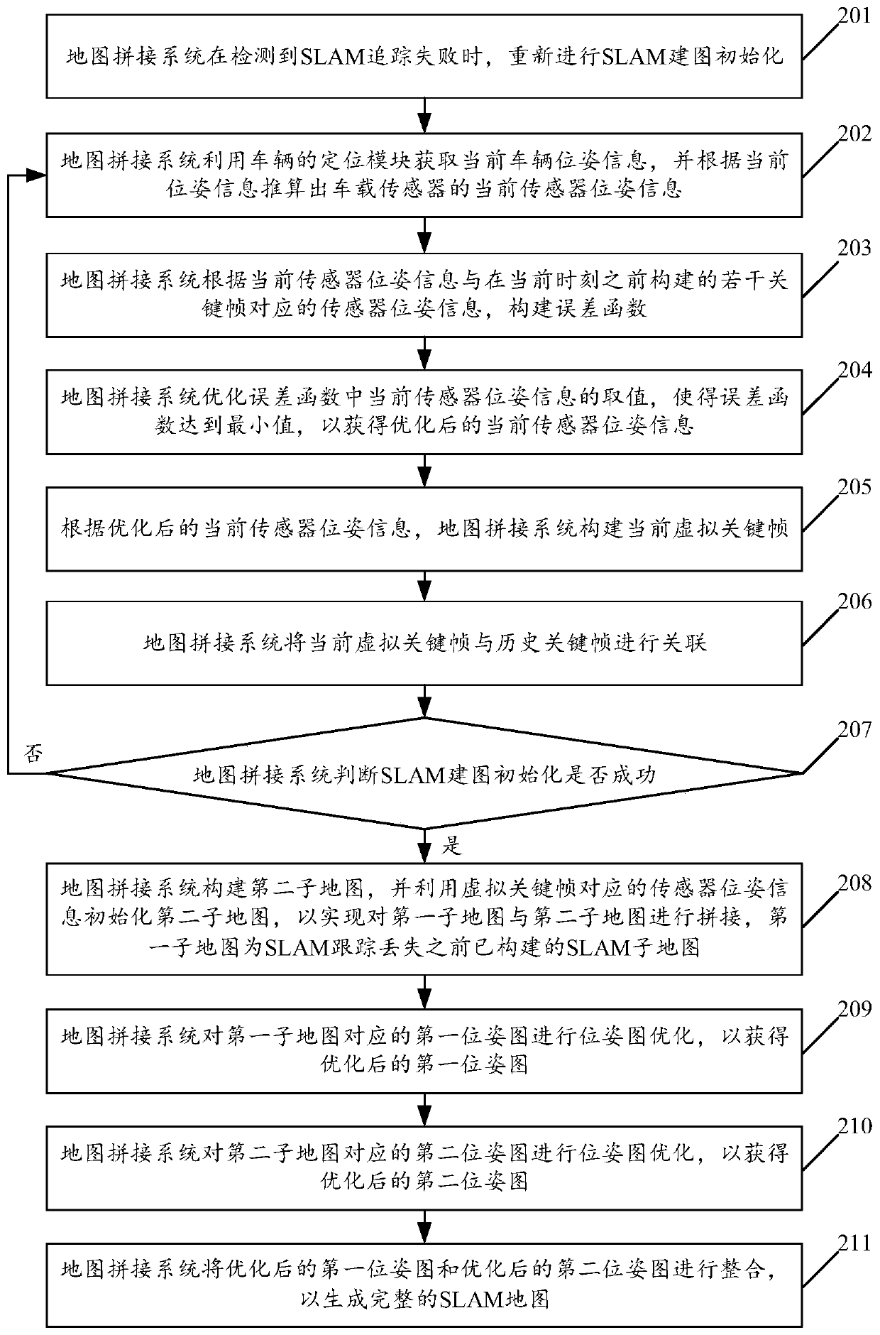
[0096] see figure 2 , figure 2 It is a schematic flowchart of another SLAM map stitching method disclosed in the embodiment of the present invention. like figure 2 As shown, the SLAM map stitching method may include the following steps.

[0097] 201. When the map stitching system detects that SLAM tracking is lost, it re-initializes SLAM mapping.

[0098] 202. The map stitching system uses the positioning module of the vehicle to obtain the current vehicle pose information, and calculates the current sensor pose information of the vehicle camera according to the current vehicle pose information.

[0099] 203. The map stitching system constructs an error function according to the current sensor pose information and sensor pose information corresponding to several key frames constructed before the current moment.

[0100] In the embodiment of the present invention, the several key frames constructed before the current moment may be at least two key frames in the first sub...

Embodiment 3

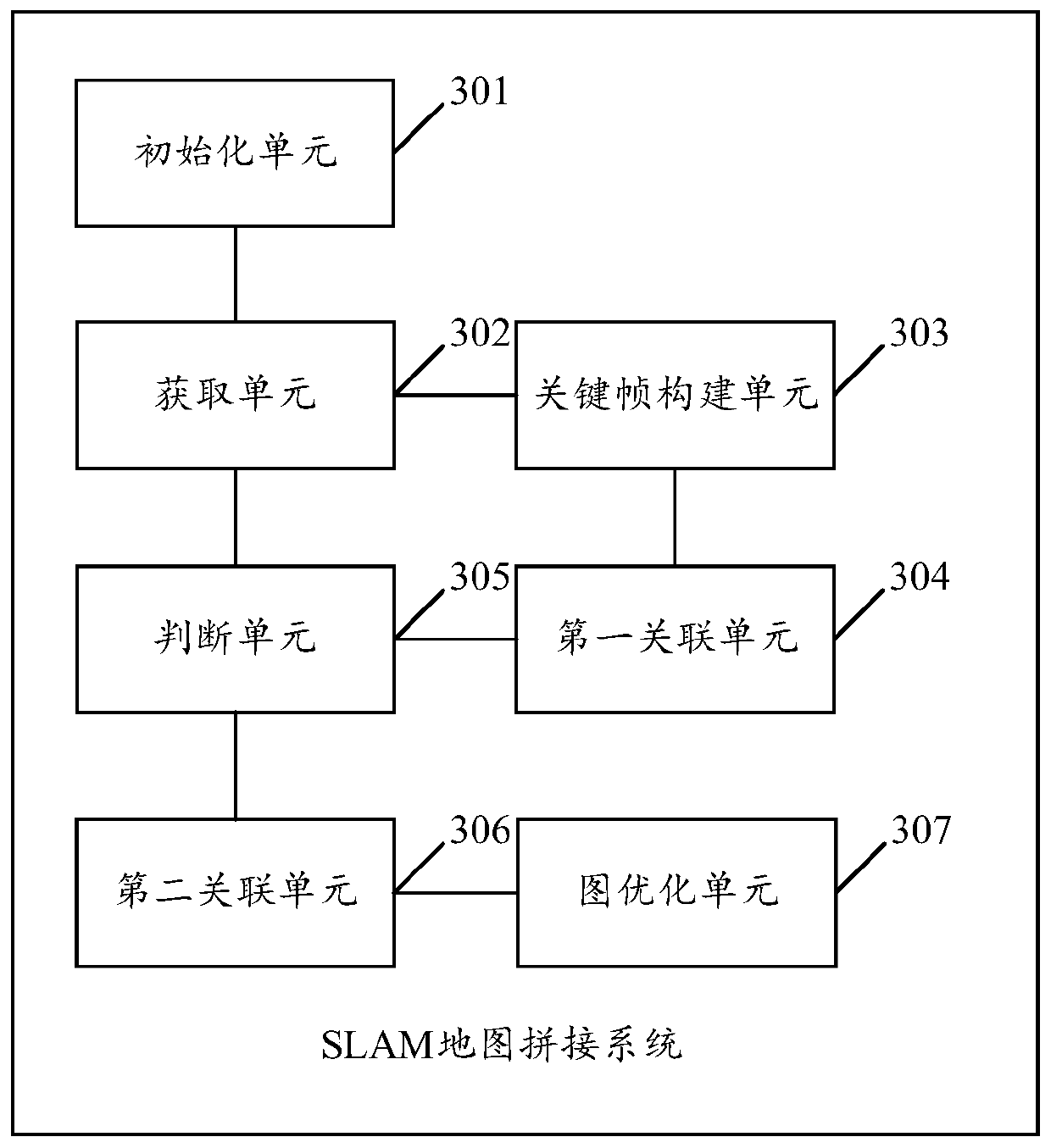
[0121] See 3, image 3 It is a schematic structural diagram of a SLAM map mosaic system disclosed in an embodiment of the present invention. like image 3 As shown, the SLAM map stitching system may include an initialization unit 301, an acquisition unit 302, a key frame construction unit 303, a first association unit 304, a judgment unit 305, a second association unit 306, and a graph optimization unit 307, wherein:

[0122] The initialization unit 301 is configured to re-initialize SLAM mapping when SLAM tracking loss is detected.

[0123] In the embodiment of the present invention, optionally, for visual SLAM mapping, the steps for initialization unit 301 to re-initialize SLAM mapping may specifically include:

[0124] The initialization unit 301 is configured to continuously collect image frames through the visual sensor, and perform feature point identification on the collected image frames; if the current image frame meets the requirement for the number of feature poin...


PUM


Abstract

The invention discloses an SLAM map splicing method and system, and the method comprises the steps of carrying out the initialization of SLAM mapping again when the loss of SLAM tracking is detected;using a positioning module of the vehicle for obtaining the current vehicle pose information, and calculating the current pose information of the vehicle-mounted sensor to construct a current virtualkey frame; associating the current virtual key frame with a historical key frame, and judging whether initialization is successful or not; if not, using a positioning module of the vehicle for obtaining current vehicle pose information to generate a virtual key frame; if yes, constructing a new sub-map, and initializing the new sub-map by using the sensor pose information corresponding to the current virtual key frame, so as to realize the splicing between the original sub-map and the new sub-map; and meanwhile, carrying out overall joint optimization on all the sub-maps. The technology solvesthe problem of drawing failure caused by SLAM tracking loss in the SLAM drawing process, and the success rate of constructing a large-scene complete SLAM map is greatly improved.

Description

technical field [0001] The invention relates to the technical field of automatic driving, in particular to a SLAM map splicing method and system. Background technique [0002] In recent years, Simultaneous Localization And Mapping (SLAM) technology has been increasingly used in the field of autonomous vehicles, mainly to solve the problem of vehicle positioning and map construction when moving in an unknown environment. Among them, the traditional SLAM map construction process is mainly: the vehicle collects observation data (such as captured images, point cloud data) of the surrounding environment through on-board sensors (such as cameras, lidars) to track and match the collected observation data. ; According to the matching relationship between the observation data, the pose motion information corresponding to the vehicle sensor is calculated, and then the vehicle itself can be positioned, and an incremental map can be constructed based on the vehicle positioning informati...

Claims


Application Information

Patent Timeline
IPC IPC(8): G06T11/20G06T3/40G01C21/30
CPCG06T3/4038G01C21/28G06T7/248G06T7/74G06T2207/10016G06T2207/10028G06T2210/61G06T2207/30241
Inventor 周建刘中元李良肖志光
Owner GUANGZHOU XIAOPENG MOTORS TECH CO LTD
Why Eureka
Try Eureka