Device and method for cleaning and drying wafer and chemical mechanical grinding table

A drying device and drying method technology, applied in electrical components, semiconductor/solid-state device manufacturing, circuits, etc., can solve the problems of increased wafer surface residues, cluster residue defects, and increased drying and cleaning difficulty.

Active Publication Date: 2019-06-14
SHANGHAI HUALI MICROELECTRONICS CORP
View PDF21 Cites 5 Cited by
  • Summary
  • Abstract
  • Description
  • Claims
  • Application Information

AI Technical Summary

Problems solved by technology

The current mainstream chemical mechanical polishing machines basically have their own cleaning and drying functions. During the wafer drying process, the machine mainly uses a gas mixture to purge the wafer surface to clean the brush residue and take away the residue on the wafer surface. Moisture achieves the purpose of drying, the increase of grinding residue and the decrease of brush cleaning ability will increase the residue on the surface of the wafer entering the drying tank, and the downward blowing of the spray bar will make the residue gather downward, making it difficult to dry and clean, and it is easy to form cluster residue Physical defects

Method used


Image

  • Device and method for cleaning and drying wafer and chemical mechanical grinding table
  • Device and method for cleaning and drying wafer and chemical mechanical grinding table
  • Device and method for cleaning and drying wafer and chemical mechanical grinding table

Examples


Embodiment Construction

[0022] The specific implementation manner of the present invention will be described in more detail below with reference to schematic diagrams. Advantages and features of the present invention will be apparent from the following description and claims. It should be noted that all the drawings are in a very simplified form and use imprecise scales, and are only used to facilitate and clearly assist the purpose of illustrating the embodiments of the present invention.

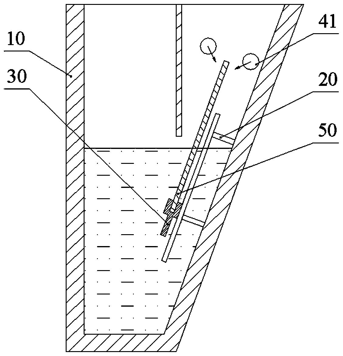
[0023] After the wafer is ground, the surface of the wafer will remain with polishing liquid and foreign matter. The current mainstream chemical mechanical polishing machines basically have their own cleaning and drying functions. During the wafer drying process, the machine mainly uses a gas mixture to purge the wafer surface to clean the residue after brushing and take away the wafer. The water vapor on the surface achieves the purpose of drying. figure 1 is a schematic diagram of an existing wafer cleaning a...


PUM


Abstract

The invention discloses a device and method for cleaning and drying a wafer and a chemical mechanical grinding table. The device includes a drying tank, an object stage, a transfer arm and two first spray rods, the two first spray rods are arranged in parallel in the drying tank, the object stage is arranged on one side wall of the drying tank, the transfer arm carrying the wafer is movable upwardly along the object stage and passes between the two first spray rods, the first spray rod is provided with a plurality of obliquely downwardly opposite nozzle holes along the rod body, and the middleportion of the first spray rod is recessed downwardly so as to make the jet direction of the nozzle holes face outwardly. A gas mixture ejected from the first spary rod blows the residue on the surface of the wafer away from the edge of the wafer, reduces the accumulation of the residue along the lower edge of the wafer, avoids the accumulation of the residue to form a cluster residue defect, andimproves the yield.

Description

technical field [0001] The invention relates to the technical field of semiconductor manufacturing, in particular to a wafer cleaning and drying device, method and chemical mechanical grinding machine platform. Background technique [0002] The CMP (Chemical Mechanical Polishing) process was first introduced into the semiconductor manufacturing industry by IBM in the late 1980s to solve the problem of flattening the surface of silicon wafers. key technologies. CMP mainly relies on the relative movement between the wafer and the polishing pad and the chemical erosion of the polishing liquid to achieve the purpose of grinding and removal. The machine used for chemical mechanical polishing generally consists of a chip mechanical transfer device, a grinding device, and a cleaning and drying device. The wafer is transferred by the transfer device to the grinding device for grinding, and then transferred to the cleaning and drying device for cleaning and drying. [0003] After ...

Claims


Application Information

Patent Timeline
Patent Type & Authority Applications(China)
IPC IPC(8): H01L21/67H01L21/02
Inventor 曹孟云
Owner SHANGHAI HUALI MICROELECTRONICS CORP
Why Eureka
Try Eureka